Category Archive: Spin Testing

Spin Testing Improves ePropulsion Rotor Design

Developing sustainable transportation solutions is an increasingly high-priority goal in the aviation industry. Amongst the emerging contenders of electrified aircraft, exciting trends include the development of delivery drones and air taxis (eVTOLs). These new vehicles are designed to fly at low altitudes over heavily populated areas, requiring focused attention on its electric propulsion systems for noise minimization and design redundancy that provides safe-to-fail measures. 

The demand for more efficient and power-dense electric propulsion systems is set to increase steadily. To make them flight-worthy, makers of propulsion systems must fulfill the airworthiness requirements, which typically require rigorous analysis and validation testing. 

Test Devices by SCHENCK supports these emerging technologies with industry-leading spin testing services. These services aid in design development and the eventual certification of ePropulsion rotors. This article will discuss the types of spin tests involved in electric propulsion testing, the benefits associated with these services, and what the future holds for eVTOL certification. 

What is a Spin Pit?

centrio 100 spin testerThe rotating parts in eVTOL motors are critical to safety and operation, and they must be thoroughly tested before they can enter into service. Typically for a flight-worthiness certification, critical rotating parts in aircraft are tested for their structural integrity and fatigue durability. Whether it is an overspeed test or Low Cycle Fatigue (LCF) test, the parts are pushed close to their strength and durability limits, and it is not uncommon for them to fail during the test. High-speed rotors store a significant level of kinetic energy, and they often fail suddenly and violently. If not prepared, the rotor failure event could result in a catastrophic event.

A spin pit is a purpose-designed machine specialized in testing high-speed rotors safely. 

At Test Devices by SCHENCK, we perform various types of spin tests for electric propulsion rotors by using our purpose-designed spin pit. The latest model of Schenck’s Centrio 100 spin tester features a fortified test chamber designed to contain hazardous rotor bursts and their subsequent fragments while offering many automated features to streamline the setup and execution of tests. The system also offers various test conditions (ex. elevated temperature conditions) and advanced data measurement options (such as a rotor expansion measurement system).

Why Spin Test?

Compared to other testing methods, spin testing reveals important data about rotor design. Some of the key benefits of spin testing include:

  • Cost and schedule benefits. Since spin testing tests the rotor by itself, there is no need for additional auxiliary hardware such as the bearings, stator, or VFD. Compared to a full-system test, spin testing offers a more pragmatic and economical method to set up the desired test conditions and instrument the rotor for data measurements. This is especially true when a rotor needs to be tested outside of its typical design envelope.
  • Risk management. As explained earlier, the spin pit addresses the safety risks associated with a rotor burst. In addition, spin testing also alleviates the risk of premature test termination from the failures of auxiliary systems or parts.  
  • Early phase evaluation. Spin testing allows engineers to test variations of rotor design separately from other components or subsystems. Doing so enables engineers to generate useful engineering data to fill the information gap and optimize the rotor design. The data can be used to mature the numerical model, accelerate design maturation, and boost confidence in first article success.

Spin tests provide critical data and information to evaluate the performance, safety, and operation of critical rotating parts. Doing so saves time and helps to avoid costly and painstaking investigative work that could emerge as a result of partially validated rotor designs. Partnering with an industry expert like Test Devices by SCHENCK can help you bridge the information gap and accelerate your product development cycle. 

Types of Spin Tests

When testing ePropulsion rotor design, there are three types of spin testing methods: overspeed, burst, and LCF testing. Each of these testing services offers unique information on the durability and structural integrity of a rotor’s design. 

Overspeed Test

Also known as a proof test, the goal of an overspeed test is to validate structural stability and integrity. Overspeed testing is performed by spinning a rotor above its typical operating ceiling. During the process, the rotor will be examined for several changes in behavior: 

  • Linear elastic or plastic deformation
  • Changes in unbalance level
  • Changes in the rotor outer diameter (OD) profile

As a result of this testing process, we can help minimize the risk of unexpected rotor dynamic instabilities and confirm the rotor’s structural integrity. 

Burst Test

A burst test involves spinning a rotor until it ruptures under a centrifugal (CF) load. The goal is to observe and confirm the limit and the failure mode of the rotor, as this information is key for improving its safety and structural integrity. During a burst test, a high-speed video camera setup within the spin pit captures imaging of the burst event. An in-depth understanding of the rotor’s failure mode can give key insight into a better-performing design.  

Low Cycle Fatigue (LCF) Test

LCF testing is an important method of evaluating a rotor’s durability. It involves cycling the rotor through tens of thousands of speed cycles, either in ambient or elevated temperature conditions.

The test temperature for electric motor LCF test is typically in a low threshold (200°F-500°F). However, this does not diminish the importance of accurately controlling the test temperature, as its effect is relative to the material property of the rotor. At Test Devices, we take extra care to avoid unintentional heat damage that could compromise the accuracy of the test result. 

Benefits of Using Test Devices by SCHENCK’s Spin Testing Services for ePropulsion

At Test Devices by SCHENCK, we offer everything you need for ePropulsion rotor testing and balancing. Our extensive background in spin testing for ePropulsion systems delivers many benefits for our clients, including: 

  • Full engineering support from test concept development to project management and final reports
  • Access to a world-class testing facility with an onsite machine shop for expeditious hardware adjustments
  • Test instrumentation expertise, including expansion measurement and high-speed video imaging
  • Pre- and post-test inspection capabilities, including balance measurements and CMMs
  • Testing standards that adhere to the AS9100 aerospace standard

The Future of Spin Testing for Electric Motors

Modern spin testing techniques for electric motors offer valuable data for accelerating and advancing state-of-the-art rotor designs for high-performance electric motors. eVTOL motor rotors are complex assemblies that feature composite structures (vs. homogenous) that make them difficult to model.

The data from spin testing bridges this information gap, serving as a proven technique for CF load testing and offering a variety of test environments and data measurement options. The data derived from spin tests enhance rotor safety while helping tune the analytical models and deepen the understanding of rotor behavior and failure modes. Spin tests also allow earlier testing to be performed, eliminating assumptions and uncertainties while smoothing the path toward eVTOL certification. 

Spin Testing Services From Test Devices by SCHENCK

Test Devices by SCHENCK is a global leader in balancing technologies and high-speed rotor engineering. Our spin testing services are a critical element of manufacturing high-quality rotating parts that deliver greater efficiency and increased service life. As a partner in climate-neutral mobility, we can help you develop eMobility solutions that reduce environmental pollution and noise emissions. For more information on our electric motor testing services, contact us or request a quote today.

How to Eliminate Noise and Vibration From eVTOLs?

Noise, vibration, and harshness (NVH) is a key concern that influences driver and passenger experience in the automotive industry. NVH is a challenging quality to engineer because it is subjective from person to person, as well as the context of the passenger experience. NVH is also an important topic for the aerospace industry. Not only do vibration and noise levels affect passenger flight experience, but they also must comply with local sound pollution restrictions.

NVH is of particular concern for eVTOL (electric vertical take-off and landing) vehicles, which are preparing to launch air taxi services into urban settings in the near future. Learn more as to why NVH is such an important topic to consider when engineering eVTOL vehicles.

Why Do Noise, Vibration, and Harshness Matter for eVTOLs?

At best, excessive noise and vibration are annoying, but prolonged exposure to relatively tolerable levels of noise and vibration could lead to health problems—like stress, fatigue, headache, and hearing loss. Sustained high levels of noise and vibration could cause machine issues including loss of horsepower, fatigue cracks, and instrument failure. In any vehicle, the common sources of noise and vibrations are the engine, transmission, and propulsion system. Thus, designing a new system requires careful considerations and mitigation plans to eliminate undesirable noise and vibration, especially for mass produced products.

e-propulsion

Typical solutions involve isolating the source of excitation, applying dampeners, and detuning structural resonances. However, these fixes typically require adding more mass and weight to the aircraft or redesigning its structure (trading off the performance). Solving NVH issues can quickly spiral into expensive endeavors if not thought through carefully in the design stage, and the problem could scale massively with mass produced products.

Eliminating the Noise & Vibration from the Source

The electric motors for the propulsion systems in eVTOLs and electric aircraft are the subject of interest. Their design and the manufacturing plan are critical to managing noise and vibrations. Emerging prototypes of the aircraft show the use of radial/axial flux types. Some hybrid designs plan to use onboard power generators, which are driven by sustainable alternative fuel (SAF) powered turbines. 

Any rotating part is subject to problems relating to unbalance; uneven mass distribution around the axis of rotation. A common cause of unbalance is due to manufacturing deviations, but in-situ deformation can be a more relevant cause for high-performance lightweight rotors for aircraft propulsion systems. A well-designed rotor balancing and blade moment weighing strategy—paired with a detailed understanding of how rotors behave in certain operating conditions—can reduce noise, vibration, and harshness from their source.

Choosing an Industry Leader in Test Devices by SCHENCK

Leveraging spin test data, and the true expertise in rotor balance engineering, our customers can feel confident in managing their NVH concerns. SCHENCK USA offers cutting edge testing expertise and industry-leading balancing equipment backed by over 50 years of experience. 

Among our range of products and capabilities, we perform spin testing, blade moment weighing, and rotor balancing, which are all essential to the success of eVTOLs and other e-propulsion systems. Our reputation for innovation, safety, and reliability is proven, and we have been helping clients in the aerospace, energy storage, power generation, air handling, automotive, medical devices, and electronics industries with the toughest rotational testing challenges.

These industries rely on us for quality testing products and services. To learn how we can serve your industry, contact us today.

Success for the HQ-1 Spin Test System

Shops and factories need to regularly test rotors to ensure excellent performance and adherence to design or production requirements. The HQ-1 Spin Tester is a purpose-built bench that incorporates all basic spin testing.

HQ-1 is designed for manufacturing environment, and most suitable for spin testing:

  • High-speed electric motor armatures
  • Small gas turbine disks and bladed disks
  • Turbochargers & turbopump rotors
  • Electronics: Munition fuses and sensors
  • Centrifuge wheels

The HQ-1 Spin Tester is an efficient, cost-effective option for facilities that need in-house, high-quality spin verification.

HQ-1 Spin Test System Overview

Test devices spin rig in facility with computers in foreground

Our HQ-1 Spin Test System offers the following components and capabilities:

  • Compact design: The skid-mounted device can fit in a 10′ x 5′ x 6.5′ envelope for easy transportation and maneuvering.
  • Ease of use: The wheel mounting arbor fits multiple exchangeable adapters so facilities can test a variety of equipment with the same unit.
  • Drive system: The system’s default drive device can run up to 100,000 RPM as a baseline speed. Our team can provide higher speed drive options upon request.
  • Turnkey solutions: The HQ-1 Spin Tester offers plug-and-play installation, easy integration, and ERP and IoT connection capabilities.

The HQ-1’s user control system makes the device easy to operate. The interface is intuitive and has manual, semi-automatic, and automatic settings. Facilities can create pre-programmed spin cycle sequences for routine testing with built-in safety and diagnostics.

The device can be operated with an optional touchscreen interface. This offers menu-style setup, one-push operation, and barcode scanning to activate specific test sequences. Test Devices can also enable spin test systems with upgrades for remote control and monitoring for more customizable usage.

Safety

Spin tests generate significant speed and force. To keep workers and adjacent equipment safe, we build our spin test systems to exacting standards. The test chamber of the HQ-1 Spin Tester has a high-strength containment shell made from steel, is fully enclosed and includes a safety door for the operator.

We also outfit the chamber with multiple safety interlocks to protect against malfunction and abnormal machine behavior during operation. The system performs self-diagnostic tests, monitors its operation and keeps an automated log of alarms.

The vibration monitoring system in the drive unit adds another layer of safety against potential and serious hazards in the high speed testing. The system detects abnormalities and interrupt the spin operation  preventing the operators from being exposed to a potentially hazardous rotor behavior. T

Contact Test Devices to Request a Spin Test System Today

Spin testing is a step to evaluate the quality of rotating parts in manufacturing, repair, and operation. The HQ-1 Spin Tester is a purpose-driven tester that includes a fully-sealed testing chamber with a robust containment, a easy to use operator interface, and dependable in-built monitoring and safety features.

Test Devices specializes in creating high-quality testing equipment to keep your facility safe and ensure you deliver high-quality finished products. We’re the leading experts in both spin testing and balancing services, and our company is ISO 9001:2015 and ASD9100D certified. Request a quote here for more information on an HQ-1 Spin Tester for your operation today.

Industrial Applications of Spin-Testing and Balancing

Precision testing of high-speed, high-performance motors and rotors is of paramount importance in today’s aerospace, automotive, and defense industries. 

Spin testing is performed to validate the design, durability, balance, and structural integrity of the motor. The material and structural behavior of the rotor, which ties to the efficiency of a machine, is of major import across the many varied applications of electric motor technology, ranging from UAVs and UAMs to hybrid and electric vehicles. Industries that depend on high-speed rotating machinery rely heavily on test results to accurately predict how their technology will perform in real-world situations. 

Applications of Spin-Testing

spin-testing Proof and overspeed testing are standard for manufacturers of rotating equipment and turbomachinery. Simply put, overspeed testing validates the rotor integrity against the speed of the rotor to a rate far greater than what the component will encounter  in its operation. For example, FAA certification of aircraft turbines disk mandates overspeed testing before the engines can be used in aircraft. 

There are myriad tests that may be relevant based on the specific type of rotor application. For example, rotors fabricated from a new materials or constitute a radically new designs are subjected to more rigorous testing to certify for relevant regulatory standards and operational safety requirements, as well as gather as much data as possible about the effectiveness of the new technology. In this case, Test Devices could help conducting advanced spin testing to design and implement the test, and measure the critical data to evaluate the performance of the part. 

At Test Devices, we possess a broad variety of spin testing capabilities suitable for various testing scenario, including:

  • Proof spin and overspeed testing for compliance
  • Rotor strength and material evaluation via burst test (with high-speed imaging)
  • Rotor durability and fatigue evaluation via LCF testing
  • Heated and thermal gradient test to capture the accurate material conditions
  • Rotor growth and profile mapping – Capture the material behavior under CF load

Balancing

Proper balancing is an essential step to ensure the reliable operation of any type of rotor. Even a small unbalance can result in problems ranging from unexpected rotor wear to catastrophic equipment failure. 

balancing-services-test-devicesUnbalance is inherent in any real-life rotors. Even the minute variation within the manufacturing tolerances, and uneven distribution of material properties about the axis of rotation could cause the bias in the distribution of the CF load in a rotor that results in undesirable vibration. 

In some cases, involving high-speed rotors, more complex scenario must be considered. Unexpected deformation of rotor due to the emergence of plasticity or shift in the internal structure of a rotor (e.g. winding settling in the motor armature) could result in an unintended unbalance. In such a scenario, the combination of both spin testing and balancing plays a critical role in identifying and resolving potential problems in the rotor.

As such, proper balancing is a critical step to the successful function of rotating components. An unbalanced condition can be very hazardous and may result in severe damage to machinery, threaten the safety of equipment operators, and drive up costs due to redesigns.

Spin testing and balancing plays a critical role in ensuring the safe and reliable operation of the final component, ensuring its integrity and reliability – optimizing the performance and extending the machine’s useful life. 

Advanced Spin Testing Services from Test Devices

Test Devices has more than 40 years of experience in advanced spin testing practices. Our state-of-the-art equipment and highly trained staff of engineers and technicians offer innovative solutions to the challenges facing designers and manufacturers of rotating components.

We can help you optimize your designs and accelerate your development and production process by providing you with all the relevant test data that you need.

Contact Us today for more information about our spin testing services or to discuss your design with one of our experts.

Spin Testing Additively Manufactured or 3D-Printed Parts

Additive manufacturing (AM) is the process of building 3D workpieces layer by layer. Rather than traditional processes such as machining, which create forms by removing the material from stock material, additive manufacturing “prints” layers into a part from a computer model created with Computer Aided Design (CAD) software.

The AM technique has been around for some time. With recent advancements in technology, it has been gaining more popularity and relevance. The AM techniques are also known as:

  • 3D Printing
  • Rapid Prototyping (RP)
  • Direct Digital Manufacturing (DDM)
  • Layered Manufacturing
  • Additive Fabrication

With the ongoing improvement on the quality of parts made with AM method, it is also becoming increasingly cost-effective. Many industry leaders believe that AM will soon become an integral part of new products and future manufacturing processes. AM technology is in the midst of a revolution, and manufacturers continue to see new benefits from new methods as they enter the market.

Why 3D Print High-Speed Rotor Parts?

Leading turbomachine OEMs are looking into a possibility of additively manufacturing high-speed rotor parts. Within the AM technologies for printing metal parts, one of the immediate areas of application for the AM parts is the replacement of (or enhancement of) traditionally cast parts.

There remain many challenges ahead of where we are today. Many manufacturers have begun to weigh the benefits of additively manufacturing the rotors with airfoils, cooling channels, and many intricate features. The potential benefits of AM for OEMs include:

  • Equivalent or stronger than min-property cast parts
  • Consolidation of multiple parts – Reduced manufacturing cost
  • Enabling new designs which cannot be made with traditional manufacturing techniques

GE and other industry leaders have waylaid some of these concerns by building functional turbine engines using 3D printing. The electron beam from one machine can fabricate many static engine parts, and recent demonstrators showed a possibility to manufacture a blade from titanium aluminide powder, a material so brittle that it could previously only be fabricated using expensive molding processes.

Along with challenges in achieving higher dimensional accuracy and better surface finish, one of the challenges in additively manufacturing a high-speed rotor is that the parts must be reliably made and validated. It is understood that the AM process has not resolved the problems related to internal defects such as material porosity, discontinuity, and directionality.

High-Speed Spin Testing is Critical for Development

Test Devices (TDI) has been spin testing cast rotors for years. With the emergence of additive manufacturing, we are starting to work with some customers to spin test their rotors. High-speed spin tests can be used to stress the parts and verify their structural integrity.

Looking further, TDI is evaluating the benefit of pre-spinning the casted or additively manufactured rotors to achieve the following benefits:

  • Stabilizing the material and minimizing the in-operation change in unbalances
  • Application of pre-spinning process to the rotors to bake-in advantageous residual stress state
  • Improving engine efficiency through controlling the rotor growth behavior and improving tip clearance

Spin Test Additively Manufactured Rotor Parts with Test Devices, Inc.

TDI continues to look into advancing and improving our spin testing technologies and services. We strive to be your “One-stop Shop” and offer comprehensive services to meet your spin testing and manufacturing needs (pre-spin, pre, and post-spin machining, balancing).

TDI offers fully compliant operation in accordance with AS9100/ISO9001 (+ OEM QPR) certified processes, backed by the demonstrated capabilities:

  • Handling high-volume loads of 6,000+ units
  • Managing 30+ manufacturing spin operations consisting of different parts of varying designs and sizes
  • Fast turn-around and guaranteeing high-quality work achieved by in-house inspections/quality assurance, machining, and balancing capabilities

Spin testing can contribute to enhancing the safety and the performance of additively manufactured rotors. Contact TDI today to learn more about spin testing 3D printed parts.

Download Your Copy Here >>

Spin Testing for Manufacturing 101

In the quest to produce stronger, more durable, and cost effective rotating parts, manufacturers are turning to spin tests to help achieve these goals. Spin tests for manufacturers can be used to validate the stability and integrity of a part, or to enhance the desirable properties of the material. We will explore the differences between traditional spin testing and spin testing for manufacturing purposes. We will also discuss the benefits of spin-testing your rotating parts, the subtle but important factors necessary to run successful manufacturing spin operations, and the importance of finding the correct spin testing service provider for your specific needs.

Jet engines, power turbines, turbochargers, electric motors — all of these high-speed rotating parts are critical for a wide range of modern high-performance machines and key infrastructures. In order to ensure optimal reliability, durability, and quality, these components must undergo rigorous engineering and testing processes.

Spinning at high speed, a machine part, such as a jet engine disk, stores a significant amount of rotational kinetic energy. In the event of a part failure, this stored kinetic energy is released, and the end result can be catastrophic. To prevent this, a spin test is conducted to evaluate the structural integrity and robustness of high-speed rotating parts. The data collected from this test allows engineers to better understand rotors’ failure behavior and improve the design as needed. Introduced more than half a century ago, spin testing techniques have been integral to the evolution of high-speed rotating machines.

While there are a variety of spin tests available, most of them can be grouped into one of two major categories: Spin Testing for Research and Development and Design Validation, or Spin Testing for Manufacturing.

Spin Testing for R&D and Design Validation

  • Custom-designed engineering tests used to validate the rotor design and/or certify the part
  • Typically involve a prototype, first article, or purpose-designed test rotor assembly
  • Design, build, and execution of the test should be carried out as a carefully managed engineering project
  • Test rig designs aim to maximize measurability of engineering data, and create realistic conditions during the test to simulate the relevant operating environment of the machine
  • Some examples of R&D and Design Validation spin testing include: Overspeed Certification Tests, Low Cycle Fatigue (LCF) Tests, High Temperature and Thermal Gradient Spin Tests, and Dynamic Spin/High Cycle Fatigue (HCF) Tests

Spin Testing for Manufacturing

  • Involve processing batches or a large volume of parts to specified operation and inspection steps
  • A quality-controlled manufacturing operation is streamlined to produce consistent, quality products
  • Timeliness, quality, and efficiency are the key drivers of a successful manufacturing spin operation

Achieving Repeatable Success in Manufacturing Spin Tests

While manufacturing spin tests may appear simple and uninvolved in comparison to the more complex and sophisticated R&D spin tests, the success and usefulness of all tests depends on the expertise of the team you choose to partner with. Experienced technicians and engineers will have carefully planned quality processes in place to ensure smooth testing and reliable results.

In order to deliver products to customers’ specifications both cost-effectively and on time, manufacturing spin tests must make use of robust, high-quality manufacturing systems capable of achieving success over thousands (and sometimes millions) of iterations. In order to achieve this repeatability, a holistic approach that considers the details of each step in the operational workflow must be employed.

Manufacturing spin tests can be further broken down into two categories:

  1. Overspeed Test

Overspeed tests are conducted to validate the stability of rotor balance and part integrity in a high-speed environment. Final machined parts, such as turbocharger impellers and turbines, are spun to a customer specified rotational speed to validate the parts’ integrity.

  1. Forging Pre-Spin

The forging pre-spin method involves a material conditioning process for aero-engine and power turbine disks. Semi-finished or un-machined forgings are spun to a specified speed to yield the material. There are several benefits of pre-spinning forgings and disks, but typically this work is done to enhance the stability and durability of the material and final products. Forgings are carefully inspected and monitored at each step of the pre-spin process to ensure proper material conditioning.

Manufacturing Spin Operation at a Glance

  1. Inspection: Examine the parts for any damage or anomalies; some customers also require part inspections for dimensional conformance
  2. Assemble the part with spin tooling
  3. Check rotor balancing, and perform corrections if necessary
  4. Perform a spin test; monitor rotor balance and rotor dynamic stability over the test speed
  5. Record and report the result
  6. Disassemble the part from the spin tooling
  7. Perform post-test inspections, and ship the part to the customer

Specific to forging pre-spin operations, customers also often require a “pilot run” during the earlier phase of process implementation; the pilot run is typically performed prior to launching a full-scale manufacturing spin operation. A series of pre-spin tests is performed to validate the tooling design performance and try out the handling equipment, operational processes, and documentation flow. These pre-spin tests also allow clients to confirm the material behavior (forging growth to a speed).

Several factors can disrupt successful pre-spin operations, however, including:

Spin testing circular image

Poorly Designed Spin Tooling — Performing an efficient, repeatable operation requires well-designed tooling and handling equipment. Poorly engineered spin tooling can lead to unstable rotor behavior, rotor dynamics issues, and limited reusability in the tooling — ultimately resulting in incipient, recurring issues in pre-spin operation. Successful spin tooling design depends on:

  • Tooling and handling equipment design performed by an experienced engineering team that understands the ins and outs of spin operation.
  • Years of experience designing and routinely testing different types of spin tooling for different test disks.
  • Comprehensive engineering work, from the selection of suitable materials to detailed stress and dynamics analyses of the rotor assembly. Careful engineering ensures reusability and high performance of the tooling in the manufacturing environment.

Balancing and Severe Vibration Issues — A critical step in rotating machine construction, proper rotor balancing helps ensure no time is wasted troubleshooting rotor dynamics and vibration issues. –

  • Balancing is often overlooked and performed without a real understanding of its importance. Specific to pre-spin operations, the forgings coming off the production line typically have unfinished contours and are often severely unbalanced. Adding extra steps for machining and balancing forgings, however, results in added costs and downtime. In some cases, forgings may not be able to be easily balanced. (TDI’s high-performance damper system is specifically designed to manage vibration and rotor instability problems.)

Bad Quality Processes and Material Handling — For professionals working within the strict requirements of the aerospace standard, quality processes must be kept in mind throughout the entire operation. Here’s what to look for when sourcing for aerospace standard processes:

  • Services based on the AS9100/ISO9001 quality standard, backed by experience with leading aeroengine OEMs.
  • A culture of quality that ensures every step of the spin tooling process is performed to stringent standards. Through closely monitored parts tracking and receiving to meticulous inspection and pre-spin work, there should be a guarantee that all processed parts are of the highest possible quality and reliability.
  • Highly trained staff, state-of-the-art spin rigs, CMM machines, and climate-controlled inspection rooms.
Spin testing set up

Inaccurate Speed Measurement and Control — Measuring and controlling rotational speed is critical for successful spin test operations, but this step is also often overlooked.

  • Inaccurate speed data and spin test operational records can lead to catastrophic field accidents. Whether done intentionally or unintentionally, rotors spun to an incorrect speed severely compromise the integrity of the parts and the machines.
  • In a nonconformance case with an exceeded speed target, the rotor may have sustained damage that is undetectable to inspectors.
  • In a nonconformance case with an undershot speed target, there are two likely causes: 1) The rotor was not tested properly to the requirement, or 2) The rotor may not have achieved the required material conditioning at the specified target speed.
  • Measuring, recording, and ensuring the accuracy of spin test speed is one of the most important steps in spin test operations, directly affecting the quality of the part. Plus, it’s very difficult and time consuming to examine the aftermath of an incorrectly executed spin test.
Rotor burst test close up

Rotor Bursts — Accidents can happen even in the most diligently planned and managed manufacturing environments. During spin testing, it’s important to take preventative measures to manage the risk of disk bursts, since rotors spinning at high speeds store a large amount of rotational kinetic energy that can be released in the event of a part failure, leading to catastrophic damage.

  • The first priority in managing the risk of a disk burst is ensuring optimal safety. Spin pit containment alone is not enough; facilities must take necessary measures to protect spin pit operators and surrounding equipment from unexpected containment failures. Ideally, spin pits should be placed in a purpose designed test cell with a separate operator room so that workers are not at risk.
  • Downtime in any manufacturing process can cause client dissatisfaction and added expenditures, so it’s critical to establish a practical contingency plan that will allow you to quickly respond to and recover from accidents, should they occur.
  • Specific to forging pre-spin work, operators should carefully manage the risk of disk bursts. Forgings are heavy and typically spun to a relatively high speed, which means they can cause great destruction in the event of a burst.

Learn More

For over 40 years, Test Devices Inc. (TDI) has been a leading provider of spin testing services and equipment, developing and advancing the science of centrifugal, vibratory, and thermal stress testing. Whether you’re interested in setting up your own manufacturing spin operation or looking to outsource the work, you’ll need a dependable partner to ensure optimal performance, quality, and reliability.

Since first introducing pre-spin testing services to our range of capabilities ten years ago, TDI has become a trusted partner for various leading OEMs in the development, innovation, and implementation of their pre-spin operations. As a leading expert in spin testing and related applications, our team has a deep understanding of the many small details that can affect successful pre-spin operation design and implementation. Our equipment designs and engineering solutions embody 40 years of pragmatic innovation gained from hands-on experience performing spin tests and industrial spin operations in forging pre-spin work:

  • TDI offers a high-performance drive control system built based on the latest PLC technology and TDI’s 1160 Precision Digital High-Speed Tachometer. The 1160 tachometer, built on a 16-bit digital technology platform, allows for fast and reliable speed measurement — thereby ensuring accurate control of rotors in high-rpm spin operations.
  • TDI has performed numerous burst tests for different types and sizes of rotors. With years of experience and an accident-free record for many decades, we’re proud to offer the industry’s most robust risk mitigation services against high-energy disk bursts.

For help designing a facility, production processes, and spin tooling, contact us today. Our team can provide the necessary training and expert assistance needed to implement a highly successful operation.

Test Devices 2018 Year in Review

2018 has been a banner year for Test Devices, with expansions in both our facilities and our services, allowing us to better serve our customers as a “dependable partner” and a convenient “one stop shop”. Some of our new and expanded service offerings include in-house machining, eDrive spin testing, and expanded balancing capabilities – thanks to the acquisition of a new Schenck balancing machine.

Facility Updates 

Test Devices’ latest facility upgrade brought significant improvements to our shipping and receiving departments and upgrades to our climate-controlled precision inspection room, which includes the expansion of our Quality Inspection team and the acquisition of a new larger CMM (coordinate measuring machine).

The redesigned facility layout, added floor space, and new equipment allowed us to streamline our workflow and enables us to work more efficiently than ever before. The new shipping and receiving departments are now located to the front of the building with an expanded floor space, and optimally equipped handling areas with additional cranes and staged operations. This new layout minimizes unnecessary movement, creates easier access and an unobstructed flow of materials.

We have also expanded our equipment build area and relocated it to a new section of our facility. This move allowed for a more efficient staging of equipment builds and assembly operations capable of preparing three to four machines simultaneously.

Semi-Finish Machining

As of June, Test Devices now offers in-house semi-finish machining services for aerospace turbine disks. For over a decade, TDI has served leading jet engine OEMs who require forging pre-spinning services—a vital part of producing nascent engine disks that offer the highest performance. While a seemingly simple process, this service is deeply specialized, demanding the highest knowledge and skill level to produce a seamless operation. This newly added machining capability will vertically integrate operational steps and allow TDI to offer more expeditious and higher quality services. By the end of 2018, TDI is on track to ship over 100 semi-finished forgings.

Expanding Aerospace Grade Balancing Services

In 2018, Test Devices grew our balancing capabilities by acquiring a new HM 20 Schenck Horizontal Balancing Machine to support the growing demand for these operations. This high precision, state-of-the-art machine allows TDI to service a broader range of customers with varying rotor balancing needs.

Among the primary benefits of the HM 20 is its hard-mounted bearing design, ensuring rapid changeovers between rotors, which allows Test Devices handle significantly higher volumes of balancing jobs and increase the efficiency of our operational capabilities. The HM 20’s modular design also allows it to be easily modified.

Growth in eDrive Spin Testing Systems

The successful completion of an increasing number of proof and burst tests and 130,000 LCF cycles in 2018 attests to the growing demand for eDrive testing.

We are continuing to enhance our testing and engineering offerings to support eDrive customers in 2018, including advanced rotor growth mapping, high-resolution, high-speed video imaging, expedited fatigue, LCF tests (with RT-CDS and growth mapping), heated spin tests, unbalance budgeting and rotor design engineering support.

Download Your Copy Now >>

2019 and Beyond

Test Devices Inc. continues to build our services and capabilities in 2019 and we look forward to offering better services for new and existing clients in the aerospace, automotive, and other highly technical industries. We will keep leading the industry by offering the latest services and technology.

To learn how our spin testing, balancing, and other services can help your R&D efforts, prototyping, or manufacturing operation, contact us or request a quote.

The Value of Fatigue Testing

Fatigue Testing

Fatigue testing is a crucial procedure used by engineers and technicians to help predict the durability of a part or component under its operating conditions. To appreciate the value of fatigue testing, it is essential to first understand the phenomenon.

Fatigue is a type of structural damage prevalent in cyclically loaded structures. The fatigue is characterized by an initiation and growth of cracks that will eventually result in a catastrophic fracture of a material. Unlike the structural failure caused by an overload, fatigue damage develops under the magnitude of the stresses below the material’s yield strength, and therefore tends to covertly manifest without deforming or showing obvious “warning signs”. The rate at which a fatigue crack grows is dependent on the material’s properties as well as the intensity and cycle frequency of the applied load.

Fatigue testing is used to evaluate a material’s (and component’s) structural durability by testing and analyzing its ability to withstand cyclic loading conditions.

Fatigue Testing Methods

There are different types of fatigue testing machines with various capabilities, ranging from automated material specimen tensile test machines to large full-scale structural test rigs. In a rotating structure, such as gas turbine disks and blades, accurately capturing the loading conditions in fatigue-prone features can be a complicated challenge. Rotors often have intricate geometries to serve its intended functions and these features are subject to varying degree of multiaxial stresses caused by the CF load, which also changes over the course of the operating cycle of the machine as rotor speed changes. These loading conditions are difficult, if not impossible, to capture in test methods other than spin testing.

Within the rotor specific testing techniques, Test Devices Inc. is specialized in performing different variants of LCF (Low Cycle Fatigue) and HCF (High Cycle Fatigue) tests.

The LCF regime is characterized by a higher load application, within the material’s elastic-plastic range, at low frequency (or cycle rate). For example, the take-off and landing cycle of an airplane. Typically, the HCF regime is characterized by the application of a very high-frequency load which results in a rapid accumulation of fatigue damages in a short span of time. These conditions are found in the vibrating vanes or blades subject to resonance.

Both LCF and HCF are common issues in the operation and safety of critical rotating components. Unexpected failure of rotors, such as high-speed impellers and turbine engines, which operate under high centrifugal forces often end in a catastrophic effect.

Benefits of Spin Fatigue Testing

Fatigue testing is performed to generate the data needed to validate and/or refine a probabilistic model of the components’ life in its operational environment. The way the fatigue damage initiates and develops in a material can be influenced by various factors including the loading field cycle pattern, axiality, temperature and environmental factors (e.g. oxidation and corrosion).

The result of the fatigue test data helps to define the maintenance and repair cycle requirements and the safe operating life of machines. These will have a significant impact on the cost of ownership of the equipment as well as safety-related issues.

Test Devices specializes in providing the most relevant test data to our customers who design and develop the advanced machines that are critical to our transportation, infrastructure, and national defense.

Spin fatigue testing can be used in any industry or application where the durability and integrity of a rotor and rotating component matters. Some industries that regularly use fatigue testing and fatigue testing machines include:

  • Automotive – turbochargers, tires, and wheels
  • Aerospace – jet engine components, turbine rotors, wing materials
  • Medical – prosthetics, implants,
  • Apparel – athletic shoes, textiles
  • Construction – bolts, fasteners, reinforcement bars

Learn More From Test Devices, Inc.

At Test Devices Inc., we offer both low-cycle and high-cycle fatigue spin testing services for clients who work with high-speed rotating components in demanding environments. We are capable of testing various complex and cutting-edge machinery parts for jet engines, electric motors, turbomachinery, and energy storage systems.

Our qualified and experienced engineers are willing to assist you in fatigue testing your unique part or component. If you would like to learn more about our testing services, feel free to contact our support team today.

Spin Testing for eDrive Components

Propelled by political, technological, and economic factors, growing global demand for electric vehicles (EV) has accelerated the pace of development of eDrive systems. Automotive part suppliers are developing an increasing number of sizes and varieties of eDrive systems to meet the rising number of EV models offered by all major automotive manufacturers across the international market. This development and validation of reliable electric motors is a critical part of the eDrive system.

Offering a full range of spin testing services (outlined below) to meet clients’ developmental testing needs, Test Devices is an integral partner to our eDrive spin testing customers.

As part of a developmental test program for a major eDrive manufacturer, we recently concluded 50,000+ heated cycles on a series of electric motor rotors in an effort to verify cyclic fatigue life. In addition to cyclic fatigue testing, the test program also involved a series of overspeed and burst tests to validate structural integrity.

Spin Testing from Test Devices, Inc.

With an eye on quality services and constant innovation across everything we do, our Test Devices team consistently strives to provide timely and efficient services to better meet our customers’ needs. An industry-leading provider of spin testing and balancing services, we look forward to working with customers developing eDrive systems.

Download Your Copy Now >>

For more information on our eDrive spin testing services, or to discuss how we can help with your specific testing needs, contact the team today. We’re on hand to answer any questions you may have.

TDI On Track for Growth in eDrive Spin Testing Systems

As the race for improved electric drives for electric vehicles, drones, and hybrid drive/propulsion systems accelerates, the need for testing of rotors used in high-speed electric motors is also on track for growth.

Test Devices Inc. (TDI) is pleased to begin offering detailed rotor growth testing as well as a variety of other types of spin tests and expert services to aid in the accelerated development of your high-speed eDrive motors.

Why Spin Test with Test Devices Inc?

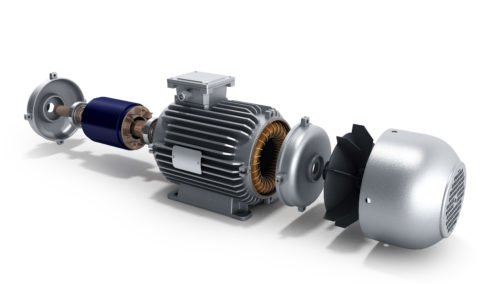
The engineering challenges faced by the high-speed electric motor industry parallel those of the jet engine industry. The need to understand rotor stresses and expansion behavior in order to accurately engineer reliable and dependable machines is a problem both sectors face. For more than 40 years, TDI has played an important role in helping industry-leading aerospace companies devise the proper tests required to study and better understand the growth of turbines and compressor disks.

In tandem with detailed rotor growth testing, additional spin test options and expert support may also assist in the development of your high-speed motors:

  • Detailed rotor growth mapping

This advanced growth measurement technique developed by Schenck is now available at TDI. This method maps the detailed contour of high-speed rotors, accurately capturing variations in a rotor’s geometry as it deforms under spinning conditions. See Figure-1 above for an example.

  • Burst test and high-speed video imaging

These tests enhance understanding of the failure limit and failure mode of the rotor. Accurate growth measurement and high-speed video data helps engineers calculate the structural stability of the rotor and its failure mode.

  • Fatigue, LCF test (with RT-CDS and growth mapping)

Fatigue and Low Cycle Fatigue (LCF) tests are useful in studying operational cycle fatigue and rotor durability. TDI’s proprietary Real-Time Crack Detection System (RT-CDS) immediately detects fatigue cracks as they happen and halts the test to preserve the damaged rotor before it disintegrates. RT-CDS enables customers to know the exact location and timing of fatigue damage, alleviating the need for painstaking failure investigation work.

  • Heated spin test

Thermal management is one of the key concerns in high-speed motor designs. Operating temperature affects material strength as well as the size of the air gap necessary for cooling airflow and accommodating rotor growth due to thermal expansion. Depending on the materials used to construct the rotors, their behavior may vary dramatically when operated at room temperature versus an elevated temperature.

  • Imbalance budgeting

TDI offers an expert design analysis service to estimate the range of imbalance levels presented by a given rotor design. This process involves analyzing the effect of the geometric tolerances of a given part and then estimating the influence on the imbalance of the rotor using a mathematical model to simulate the manufacturing process, while also comparing it to more than 10,000 different combinations of tolerance variations. The output from this analysis provides a probability model of the imbalance in the rotor, which can then be used to tune the design, minimize scatter, and avoid surprises at later stages of your fabrication processes.

Learn More

The recent merger of Test Devices Inc. (TDI) and Schenck Corporation combines the expertise of two of the most advanced leaders in spin testing, balancing, and high-speed rotor engineering. Download our eBook to learn more about why spin testing matters for eDrive systems.

Download Your Copy Now >>

To learn how our spin tests and other services can help your R&D efforts, prototyping, or manufacturing operation, contact us or request a quote.