Category Archive: Spin Testing

Optical Strain Measurement Vs. Traditional Strain Gauging

In mechanical engineering, “strain” refers to the degree and the way a structure deforms under a load. An understanding of the strain behavior, combined with the knowledge of the failure mechanisms of structural materials, allows intricate yet robust designs of modern, high-performance aerospace machines, including rocket and jet engines.

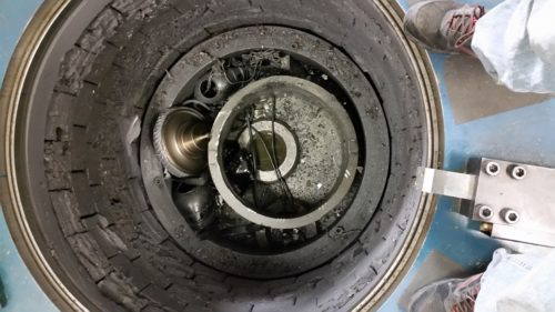
High-speed rotors, such as jet engine parts, are subject to very high stress induced by centrifugal force. The need to lighten the parts to enhance the performance of the engine must be balanced with its durability and structural integrity. Engineers must, accurately and confidently, know the stress/strain state of the rotor to make the critical design decisions.

What Is Traditional Strain Measurement?

Strain gauges are the traditional instruments employed for measuring strain. With this approach, a gauge is attached to the material being tested using an appropriate adhesive. For the purposes of spin testing, the test parts must be modified, and special tooling has to be designed to allow lead wire passages and slip rings or telemetry systems pass data from the rotating parts to the data acquisition system. Strain gauges are laborious to implement and prone to premature failure during the test, resulting in higher overall test costs, schedule overrun and less reliable test data.

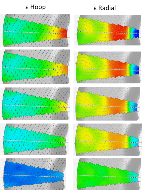
Further limitation of the strain gauges is that it is a point measurement and is blind to the behavior of the surrounding strain field behaviors. The readings from a gauge placed on a certain position of a test rotor must be interpreted accurately to perform a meaningful comparison against an FEA model.

Optical Strain Measurement Applications in the Aerospace Industry

Test Devices Inc. has been interested in a non-destructive test and manufacturing process – the Rotating Optical Strain System (ROSS) – for some time. The ROSS is a non-contact strain measurement system which eliminates limitations, is less costly and provides more complete data, possibly allowing the measurement at higher temperatures needed for fully understanding the engine parts.

The ROSS will unlock a wealth of new information for material and component designers. The data is valuable for validating (or refining) the numerical models used in designing jet engine parts and gas turbine rotating parts as well as understanding the details of the failure mechanisms limiting the performance of existing parts.

Combined with advanced spin testing capabilities, Test Devices provides a unique testing resource for civil and military jet engine/propulsion system developers. The ROSS can accelerate the development of advanced materials and manufacturing capabilities across the gas turbine industry. It can provide the most relevant data to reduce risks in currently active turbine engine development programs.

Learn More

Optical strain instruments have been on the market for years, commonly used to measure strain in static objects. But in recent years, they’ve been steadily rising in popularity as more and more industry professionals begin to use them to measure strain in high-speed spin tests.

To learn more about how these optical strain gauges can benefit your testing and production processes, reach out to the team at Test Devices today.

Exciting Facility Updates at Test Devices

As the rate of jet engine part production has rapidly increased and our clients continue to forecast further growth, we’ve become a trusted spin testing & spin process provider. To keep up with rising demand and continue to offer the most cutting-edge services available, Test Devices, Inc. has completed multiple facility expansions in recent years.

So, what’s new at Test Devices, and what do our latest expansions mean for our customers?

Facility and Capability Expansion

Our latest expansion incorporates improvements in both the shipping and receiving department and the equipment build area. We’ve also recently acquired a new coordinate measuring machine (CMM)!

  • Spin Rig Assembly Area
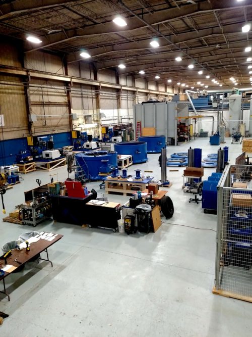
Shipping and receiving — To re-engineer the flow of parts coming into and out of our building, we relocated the shipping and receiving department to the front of the building to allow for expanded storage and handling areas along with additional cranes. In addition, the new area includes both plenty of space for trucks to back-in and an adjustable loading dock, allowing our forklifts to directly unload trailers. The relocation and improvements make unloading and loading operations significantly more efficient, contributing to reductions in turn-around time of customer parts.
  • New coordinate measuring machine — To support the needs of our growing forging pre-spin business, we remodeled our climate-controlled precision inspection room, expanded the Quality Inspection team, and added a new larger Zeiss CMM machine.
  • Equipment build area — Because of the volume of recent spin rig orders, the equipment build & assembly area was relocated to a new section of the building. This update allows for new capabilities including improved setup and staging of the equipment builds and the ability to build three to four machines simultaneously. The improved build area also features an updated air supply and electrical supply for building and testing advanced machines.

Learn More

With an eye on quality services and constant innovation across everything we do, our Test Devices, Inc. team consistently strives to provide timely and efficient services to better meet our customers’ needs.

An industry-leading provider of spin testing and balancing services, Test Devices is thrilled to announce these new facility updates, which will allow us to better serve our ever-expanding client base.

For more information on these changes, or to discuss how we can help with your specific testing needs, contact the team today. We’re on hand to answer any questions you may have.

Low Cycle Fatigue Rigs vs. Dynamic Spin Rigs

To validate the integrity of rotating parts against centrifugally loaded conditions, spin testing is a critical step to ensure rotor product quality. While the principle of the spin testing appears straightforward, it’s very easy to miss the important subtleties of the testing mechanics. In fact, since the early days of the spin testing, millions of dollars have been wasted and many perfectly good parts have been needlessly destroyed due to subpar testing practices.

Successful spin testing requires participants to:

  1. Focus on the overall test objective – Which rotor features will the test assess, and under what conditions?spin rig comparison
  2. Understand the test part – How is the test part being assembled in relation to adjoined parts in the actual operating environment? How will it interact with those related components, how will those interactions mechanically or structurally constrain the test part while under assessment, and how is the spin tooling designed to accurately represent the condition?
  3. Recognize what to test for and what results will indicate – What measurements must be taken? How should these measurements be captured so that the resulting data is useful in understanding the failure mode, validating the engineering models, and updating the part design accordingly?

Beyond the basics, spin testing can also be used to validate the durability of the rotors in more a realistic environment. Doing fatigue assessment in spin testing allows engineers to study part durability by using actual production parts (or modified versions), which would be more representative test specimens than coupons in terms of geometry, size and manufacturing process. Additionally, the loading condition resulting from the spinning would create realistic stress conditions, specifically related to the multi-axial loading field and the loading cycle.

Test Devices, Inc. (TDI) and Schenck offer two different types of spin rigs for advanced fatigue assessment tests: a Low Cycle Fatigue Rig (LCF) and a Dynamic Spin Rig (DSR). Each style of rig is designed to accommodate specific testing requirements.

  • Low Cycle Fatigue Rigs are designed to perform various low cycle fatigue (LCF) tests, which are typically used to evaluate the overall durability of parts in terms of usage or operational cycles. For example, for a jet engine for a commercial airliner, this would be based on the number takeoff and landing cycles for a specified flight path.
  • Dynamic Spin Rigs, on the other hand, are designed to test the dynamic properties of the rotor parts and its high cycle fatigue (HCF) related failure modes. The HCF is a fatigue failure mode driven by the resonance of a part; for example, turbine blades may have resonances within an operating speed range that have modeshapes tied to incipient and rapid fatigue damages/failures.

Low Cycle Fatigue (LCF) Rigs for Dependable and Realistic Testing

test devices and schenck logosTDI offers unmatched performance and reliability in its advanced LCF test spin rigs. Featuring robust armor cylinders to ensure safety, a drive system with the rapid cycle time to expedite test schedules, and accurate cycle speed control system to hit cycle targets, the rigs have been continuously proven over Test Devices’ more than 40 years of testing experience.

Combined with various automated testing features, Test Devices’ LCF rigs boast the highest-productivity drive systems available. These rigs typically incorporate a range of standard features, including:

  • Custom data acquisition system to record all test data
  • TDI’s proprietary crack detection system technology
  • Containment chamber designed to withstand high-energy burst failures
  • Vacuum system to eliminate aerodynamic losses and friction heat
  • Automated control system to perform various LCF test speed profiles
  • High performance drive systems with RPM capabilities of up to 250,000 rpm

In addition to these features, LCF rigs can also be equipped with elevated temperature test capabilities, such as:

  • Isothermal – Uniform temperature on the test rotor
  • Thermal gradient – Capability to map the realistic “engine-like” rim-to-the bore temperature profile on the rotor

Dynamic Spin Rig (DSR) for Advanced Turbine System Research

High cycle fatigue (HCF) failure typically occurs during the critical phase of an aircraft’s operations, such as during the take-off for commercial airliners or rapid throttle changes in military aircraft. While the duration of an HCF-inducing condition exposure could be brief, the damage often develops rapidly before reaching a critical level. In most cases, there is no opportunity for correction once the condition reaches this point.

DSR was developed to allow engineers to test and validate the dynamic property of bladed rotors at the component level, therefore minimizing test costs while still retaining the realism in the test. DSR are equipped with the capability to excite the bladed rotor with a desired dynamic load (of an Engine Orders, or EOs). The spin testing condition incorporates the effect of the centrifugal load on the test parts, which is known to affect its damping and resonance properties – this unique test element cannot be accurately replicated by traditional table-top methods.

Test Device’s DSRs are equipped with unique testing capabilities, which include but are not limited to:

  • Proprietary high-precision tachometer & the rpm control system to “lock on” to the target resonances
  • Oil-jet and aero-pulse blade excitation systems
  • Multi-point strain gage & slip ring (or telemetry) systems
  • No-contact Stress Measurement System (NSMS), which is also known as the Blade Tip Timing system

Testing Rigs from Test Devices

With years of experience working with cutting-edge spin test rigs, Test Devices, Inc. is proud to provide testing services utilizing both low cycle fatigue and dynamic spin rigs to customers. To learn more about our LCF and DSR spin rigs, or to discuss options for your specific application, request a quote from the team today.

Two Things to Look for in Your Spin Testing Service Provider

test devices inc control room
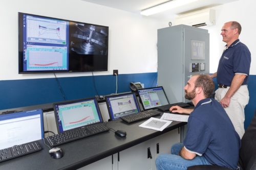
Not All Spin Tests Are Created Equal – Know the Risks

Spin Testing has been used in research & development to validate the design and the integrity of rotating components, as well as in manufacturing to process a large volume of rotating components before delivery to customers. These two applications of spin testing are vastly different in terms of set-up, output, and end goals, but there are some key common threads across all spin tests.

No matter what kind of spin testing you’re doing, there can be HUGE negative business repercussions if they are not carried out carefully, under the correct supervision, and with the correct knowledge base behind the test.

In this blog, we’ll cover two major areas that a spin test end user needs to be aware of when evaluating a potential spin testing service provider.


Control of Rotational Speed

Controlling speed is a critical component of a successful spin test, but the importance of achieving a precise test speed is not always immediately obvious to many end users.  While achieving a target rotational speed in a spin test may sound like a simple “given”, the truth is that it requires diligent work and attention to the detail.

What Happens When Rotational Speed is Inaccurate?

The data measured from engineering tests, such as a spin test, will be used to make some important decisions on the integrity and the durability of safety critical parts. The consequences of decisions made on erroneous data are serious.  In the event speed data is collected incorrectly, the overall integrity of the part can be at risk.

In most cases, bad engineering data could lead to incipient issues such as non-conformances, but it could also lead to a more serious scenario. For example, in a development of aviation jet engine, spin test results have been used to validate the cyclic fatigue durability of the rotating components.  A low cycle fatigue test (LCF) involves executing a specific rotor speed cycles over tens of thousands of iterations. The relationship between the stress caused by the centrifugal load and the fatigue life of a disk material is logarithmic, meaning a small difference in the stress (the speed) multiplies to a much larger difference, often an order of magnitude, in the resulting fatigue life values. The consequence of the difference could affect the decisions made regarding schedule and the requirements for the parts maintenance and replacement cycles, and in a more serious scenario, a premature failure of the parts when erroneously optimistic conclusions were drawn on the durability of parts.

The criticality of accurate speed data is equally important in a production environment. When a part is spun to an incorrect speed, it is often impossible to catch that via a post-test inspection. The quality of the output must be guaranteed and validated at the process step. An erroneous spin process could not only falsely “validate” parts, but also subject the component to damage.

What Can You Do to Ensure Rotational Speed is Correct?

Ensuring accurate and consistent control of spin test speed is of paramount importance for Test Devices. Designing a precise speed control system starts with being able to measure its performance precisely. Test Devices has designed and developed high-resolution precision tachometers for high-speed spin testing. Many commercially available tachometers lack the resolution, preciseness, and consistency necessary for many spin testing applications.

As a designer and a developer of the most advanced spin testing equipment, Test Devices understands the properties of spin testing equipment, including high-speed drives, to a minute detail. Combining the expertise with over four decades of spin testing experience, we developed and continue to evolve our spin test speed measurement and control solutions.

Further to the use of cutting-edge technology, Test Devices audits the test data, of all tests, to ensure its quality conformance. Understanding the importance of the engineering information we provide, as a part of our operational process Test Devices records and reports the results of the spin test (or manufacturing spin process) for every part we handle.


Quality Control and Part Handling

Spinning a part is only a step in the whole process involved in testing (or in a manufacturing spin process). The handling of your rotating components is another area that end users may often underappreciate. The mishandling of parts, and the lack of proper records of incidents can have a catastrophic impact on customer businesses overall.

What can happen?

Test Devices, Inc has seen a fair share of rotating parts that enter our facilities toting obvious signs of mishandling from previous testing services. When a part is mishandled, there is the obvious risk of the part being damaged beyond repair, and need to be scrapped. However, some damage can be so subtle, that it can go undetected and either:

1) Result in erroneous test results bad data, leading to  inaccurate conclusions about the capabilities of the component

2) Lead to total part failure later on in subsequent use after the part is assembled into the final product

spin pit debris

What Can You Do To Ensure Quality?

At the very minimum, customers should look for spin testing service facilities that conform to the up-to-date standards of AS9100 and ISO9001. It is also highly recommended that customers conduct an independent audit of vendor processes to make sure they are properly controlled according to standards. Customers should also ask potential vendors about their experience with similar projects, do research on staff experience & credentials, and review their quality processes and systems before entering into a contract.

Learn More

Interested in learning more about what other factors can disrupt your spin testing operations? Download our ebook, “Spin Testing for Manufacturing 101” for a full breakdown of what you need to know about spin testing in the manufacturing realm.
spin-testing-for-manufacturing-101-cover

"Download