


Low Cycle Fatigue Testing
The Issue
The term “fatigue”, as applied to materials and machine components, refers to the generation of cracks at stress levels that can be well below the ultimate strength of the material and even within the elastic range below the yield stress.
If undetected, these cracks can lead to failure of the component and damage or destruction of the machine.
Fatigue cracking is caused by fluctuating stress levels. It typically occurs at inconsistencies in the material such as pores or impurity inclusions but it can also occur in pristine material.
It is also prone to occur a component features that create local “stress risers” such as sharp corners or bolt holes.
Download Our Spin Testing Ebook
 Low cycle fatigue, in the practical usage of the term, generally refers to the alternating stresses caused by changes in speed of a rotating component, for example.
In turbine engines this occurs during takeoff and landing for an aero-turbine or startups and shutdowns of a power generating turbine.
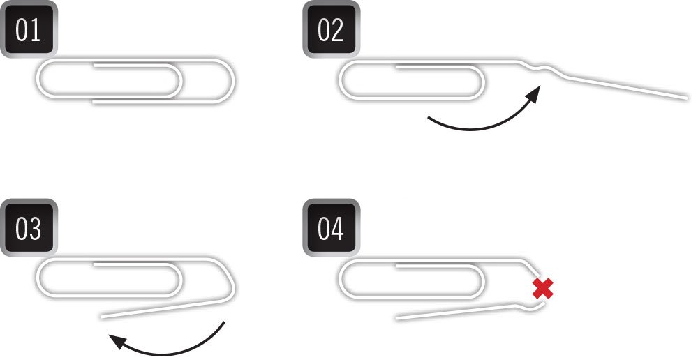
A common example of an extreme form of low cycle fatigue is illustrated in Figure 1; extreme because the paperclip is bent back and forth well into the plastic deformation regime.
Turbine components are designed to operate within only the elastic regime, nonetheless they are prone to low cycle fatigue cracking and great care is taken to determine the “fatigue life”.
Why It Matters
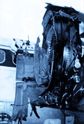
Figure 2 – Rotor failure
Failures of high-speed rotating components (engine rotors, centrifuges, high-speed fans, impellers, etc.) can endanger personnel and damage equipment.
LCF cracks often initiate at flaws in the material (impurities or voids), poor or inconsistent manufacturing processes or geometry features (bolt holes, scallops, blade slots, etc.) that create high-stress regions (hot spots).
However, even “perfect” components have a finite life.
Although high-speed equipment manufacturers design components to have sufficient fatigue life during field operation, they cannot be certain of the durability of a high-speed rotating component until the predicted behavior is validated by testing under realistic conditions.
Download Our Spin Testing Ebook
What You Can Do
The sophisticated spin testing capabilities of Test Devices are able to apply realistic boundary conditions to rotating components, including fluctuating loads, and temperatures (isothermal and gradients).
Test Devices also can utilize a patented state-of-the-art system to detect the initiation of cracks while cycling.
Our Crack Detection System can lower the cost of testing compared to stopping cycling for physical examination for cracking and it can be used to stop the test before fast fracture and total destruction of the component.
Test Devices offers LCF testing using high-power drives that can achieve short “cycle times” (the time it takes from min speed to max speed back to min).
This provides the customer with an economical means to accumulate a large number of cycles in the exploration of a components fatigue life.
Download Our Spin Testing Ebook
Advantage of Low Cycle Fatigue Testing
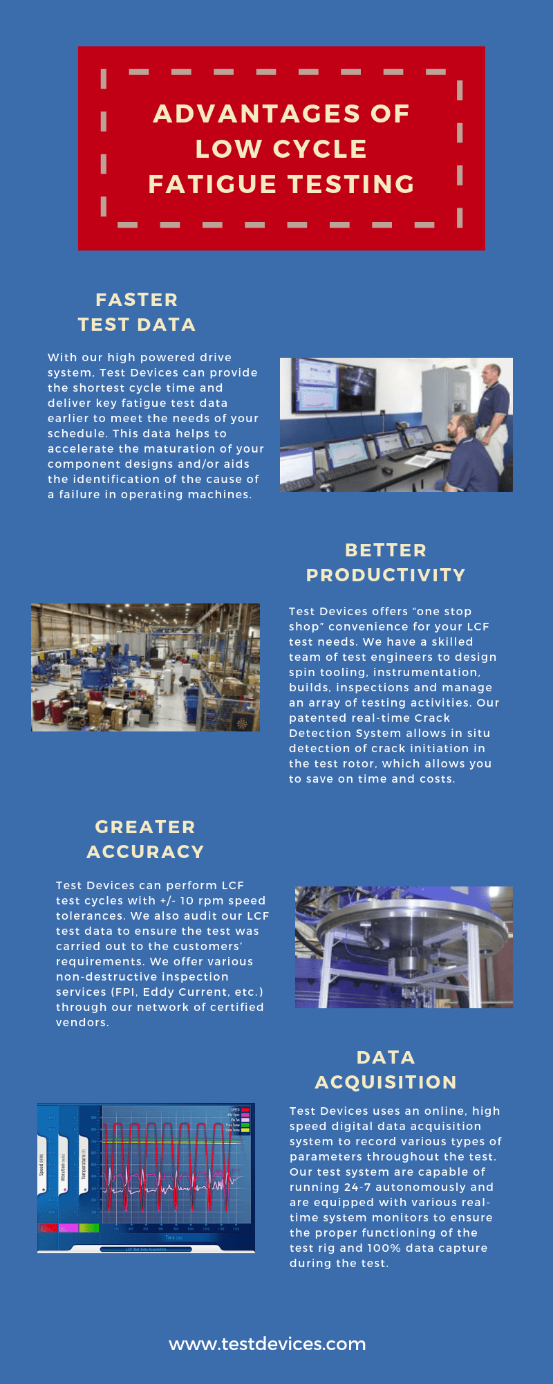
Special Purpose: Test Devices utilizes the highest productivity drive systems in the industry. Our higher power drive systems are specifically designed for LCF testing, enabling Test Devices to “fast cycle” test components. This shortens program durations, cuts costs and reduces the risk of damaging test assets.
Faster Test Data: In the event of in-field failures, Test Devices can provide critical fatigue test data earlier, which helps speed redesign of components that failed before analytical model prediction.
Data for Planning: Access to actual and model component fatigue test data enables customers to plan for design improvements or modifications proactively, rather than just reacting to unexpected results from test cells or performance data from the field.
Better Productivity: Test Devices performs LCF tests throughout the complete component speed range in robust spin test chambers designed to contain high-energy component failures. Electric motors and air turbines rapidly accelerate and decelerate test components in the shortest possible time, maximizing cycles completed per day.
Greater Accuracy: Tight speed control is an essential part of LCF testing. A component may fatigue prematurely if exposed to higher stress levels throughout the LCF test due to extreme variations in maximum cycle speed. Conversely, a test component may display an unrealistically long fatigue life if routinely cycled to a speed lower than the set maximum cycle speed. Test Devices can maintain cycle speed tolerance to ±10 rpm. Enhancements nearing completion will allow us to maintain cycle speed tolerance to ±1 rpm.
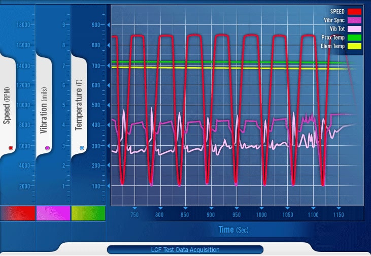
Figure 3 – LCF data acquisition
Data Acquisition: Test Devices uses an on-line, high-speed, digital data acquisition system to record all test parameters throughout the duration of the LCF test. This system replaces paper data recorders traditionally used in the industry, allowing large amounts of data to be stored, transferred and analyzed easily.
Reporting: LCF testing customers receive daily e-mail updates on the status of their project. The final report includes all cycle test data together with certificates of conformance, balance, heat calibrations, and tooling material certificates. Test data is also archived at Test Devices for the customer’s future reference.
Applications of Low Cycle Fatigue Testing
LCF testing is beneficial for any component that cycles between low and high speeds during normal operation. Components typically LCF tested include:
| Jet engine rotors | Centrifuge rotors | Turbochargers |
| Rocket pumps | High-speed fans | Composite flywheels |
| Compressor rotors | High-speed electric motors | Industrial gas turbine rotors |
| Material characterization |


