
Skip to Content
Search Exit

Author Archives: Test Devices

  1. The Testing Capabilities of Subscale Jet Engine Rigs – Part 2

    Leave a Comment

    High performance machines, such as jet engine and gas turbine parts, need to endure arduous environments for extended periods of time and perform their functions reliably time after time. The parts designed for combustors and turbine systems are subjected to harsh environments resulting from the combined effects of high temperature, combustion gas products and the CF load for rotating parts.

    Of course, performing a full-scale engine test would create the most realistic test conditions, but typically these tests can be time consuming to prepare and expensive to perform. It is also an impossible exercise in early stages when the engine and its hardware are still in design and development.
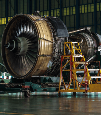
    Engineers and scientists working on the development of new materials, coating systems, sensors and part designs for new engine need test data to evaluate and refine their work. Gas burner or torch testing are much more affordable options, but they often fall short of providing the most realistic test conditions.

    Fortunately, there is a solution to address and bridge the information gap that currently exists within testing capabilities. Test Devices Inc. provides subscale jet engine testing services to customers who are looking for a more affordable and practical way to gather relevant test data with a high level of realism for materials, coatings, and sensors for new engines in development. Subscale jet engine tests can be readily used to evaluate several essential qualities, including:

    • Coating characterization, performance, and durability
    • Oxidation and corrosion
    • Creep and fatigue
    • Fuel burn studies
    • Blade high cycle fatigue
    • Volcanic ash and CMAS

    In this blog, we will discuss the value of subscale testing in coating studies and oxidation and corrosion testing. For a deeper dive into creep and fatigue testing and blade high cycle fatigue testing, be sure to check out the first part of this blog series, The Testing Capabilities of Subscale Jet Engine Rigs – Part 1.

    Engine Testing for Challenging Environments

    Jet engines are constantly subjected to harsh environments—usually for extended periods of time. Nevertheless, their components must perform consistently and reliably despite these unfavorable conditions.

    The blades, vanes and disks of turbomachines often have intricate geometries to optimize aerothermal efficiency. Because such components are routinely subjected to complex mechanical and thermal loading cycles, they can be particularly sensitive to potential damage. The designs of these parts must account for the combined effects of high CF loads, intense heat, and byproducts of gas combustion.

    For example, high pressure turbine blades operate above the melting temperature of their base composition metals. Because they are equipped with a precisely designed film air cooling system and a thermo-barrier coating (TBC), the blades can still withstand the extreme temperatures and perform the necessary function without fail.

    TBCs, however, can be compromised by oxidation and corrosion, subsequently undermining the performance of the blades themselves. As a result, durable coatings that protect the overall system from damage are essential to a successful jet engine design.

    Subscale jet engine tests can be a useful and affordable platform for studying and understanding coating and material degradation when subjected to corrosion and oxidation elements:

    • Coating damage studies via surrogate engine use a subscale jet engine as a surrogate test vehicle, modified to accommodate necessary instrumentation. The engine’s turbine blades carry the test coating in question while being introduced to corrosive chemicals for damage observation.
    • Coating and air film cooling testing uses the subscale jet engine as a hot gas generator. A plate type test specimen is instrumented with embedded thermocouples (or IR pyrometers) to monitor its operating temperature and then placed in the hot gas stream. Temperature of the exhaust gas and test plate can be controlled independently by an air-cooling system attached to the test plate.
    • Aerothermal studies and exhaust gas stream characterization is another process that uses a subscale jet engine as a hot gas generator. The test can be used to economically study the performance of a vane (or nozzle) design by using scaled prototypes manufactured from 3D printers. The use of a robotic sensor probe accurately captures the flow temperature and pressure at defined coordinates in the hot exhaust gas stream and maps the data in a 3D space to validate a CFD model and update the design.

    With subscale jet engine rigs, engineers and designers can test and study the performance of newly designed parts in more realistic test conditions, reducing the risk of “surprises” and contributing to the confidence of a successful launch and the operation of new products.

    Small Turbine Rig Testing with Test Devices, Inc.

    A small turbine test rig offers a viable alternative to pre-existing test methods, including superior test realism and several other attractive advantages:

    • Affordable: Testing on a small turbine test rig is much less expensive to perform when compared with a full-scale engine test.
    • Efficient: The ability to complete test projects in a few months rather than years
    • Flexible: It is easy to change test parameters, including adding/removing sensors and instrumentations, varying the engine or test hardware configurations.

    At TDI, we rely on our extensive experience with subscale jet engine testing to develop dependable test solutions to even the most challenging mechanical needs. To learn more about small rig and subscale jet engine testing with our team, download our eBook, The Importance of Subscale Jet Engine Testing or reach out to request a quote today.


     

    Download Our Subscale Jet Engine Testing Guide

  2. Optical Strain Measurement Vs. Traditional Strain Gauging

    Leave a Comment

    In mechanical engineering, “strain” refers to the degree and the way a structure deforms under a load. An understanding of the strain behavior, combined with the knowledge of the failure mechanisms of structural materials, allows intricate yet robust designs of modern, high-performance aerospace machines, including rocket and jet engines.

    High-speed rotors, such as jet engine parts, are subject to very high stress induced by centrifugal force. The need to lighten the parts to enhance the performance of the engine must be balanced with its durability and structural integrity. Engineers must, accurately and confidently, know the stress/strain state of the rotor to make the critical design decisions.

    What Is Traditional Strain Measurement?

    Strain gauges are the traditional instruments employed for measuring strain. With this approach, a gauge is attached to the material being tested using an appropriate adhesive. For the purposes of spin testing, the test parts must be modified, and special tooling has to be designed to allow lead wire passages and slip rings or telemetry systems pass data from the rotating parts to the data acquisition system. Strain gauges are laborious to implement and prone to premature failure during the test, resulting in higher overall test costs, schedule overrun and less reliable test data.
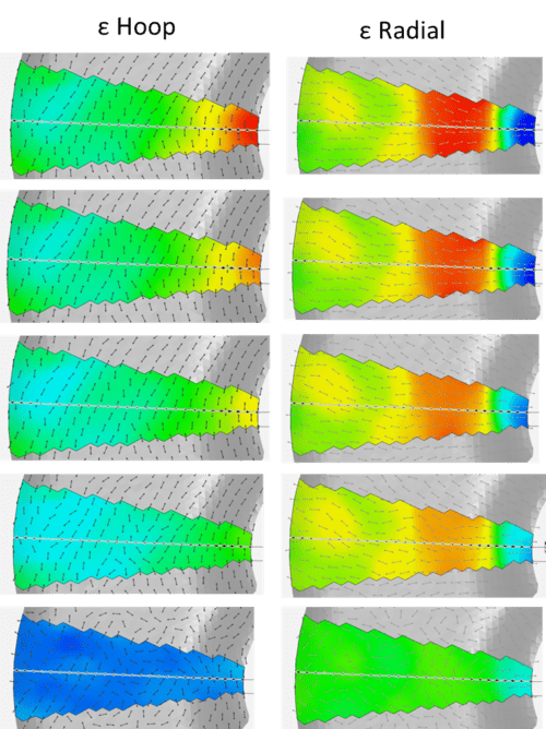
    Further limitation of the strain gauges is that it is a point measurement and is blind to the behavior of the surrounding strain field behaviors. The readings from a gauge placed on a certain position of a test rotor must be interpreted accurately to perform a meaningful comparison against an FEA model.

    Optical Strain Measurement Applications in the Aerospace Industry

    Test Devices Inc. has been interested in a non-destructive test and manufacturing process – the Rotating Optical Strain System (ROSS) – for some time. The ROSS is a non-contact strain measurement system which eliminates limitations, is less costly and provides more complete data, possibly allowing the measurement at higher temperatures needed for fully understanding the engine parts.

    The ROSS will unlock a wealth of new information for material and component designers. The data is valuable for validating (or refining) the numerical models used in designing jet engine parts and gas turbine rotating parts as well as understanding the details of the failure mechanisms limiting the performance of existing parts.

    Combined with advanced spin testing capabilities, Test Devices provides a unique testing resource for civil and military jet engine/propulsion system developers. The ROSS can accelerate the development of advanced materials and manufacturing capabilities across the gas turbine industry. It can provide the most relevant data to reduce risks in currently active turbine engine development programs.

    Learn More

    Optical strain instruments have been on the market for years, commonly used to measure strain in static objects. But in recent years, they’ve been steadily rising in popularity as more and more industry professionals begin to use them to measure strain in high-speed spin tests.

    To learn more about how these optical strain gauges can benefit your testing and production processes, reach out to the team at Test Devices today.

  3. Test Devices to Offer In-House Rough Machining Beginning June 2018

    Leave a Comment

    Test Devices Inc. (TDI) is thrilled to announce that we’ll be offering in-house rough machining services starting June 2018.

    As a part of our investment in expanding this capability, we’ll be adding two horizontal CNC horizontal lathes (Okuma), allowing TDI to become a convenient one-stop shop. Our team can now serve clients throughout every step of the process, from design to pilot run to full process deployment, all with AS9100/ISO9001 Rev D compliance.

    Forging Pre-Spin in Specialty Aviation Applications

    For over 10 years, TDI has been serving leading jet engine OEMs with forging pre-spinning services, an essential step for nascent high-performance engine disk production. Adding the rough machining capability onsite now allows us to offer shorter turnaround times and higher overall efficiency, ensuring clients’ specific needs are met as smoothly and quickly as possible.
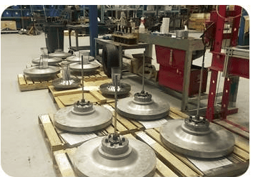
    The forging pre-spin process may seem easy at first glance, but it’s actually a highly specialized service, and requires a true expert to ensure flawless operation. These professionals must oversee:

    • Proper spin tooling design for repeated use
    • Commissioning & pilot runs
    • Confirmation and monitoring of accurate disk growth amounts
    • Troubleshooting for rotor dynamics issues
    • Optimizing and troubleshooting quality process-related issues

    Reliable Supply for Rising Demand: Preparing for Increased Aircraft and Engine Sales

    The demand for aircraft continues to grow, supporting the need for increased air travel. This trend is expected to continue its upward trajectory over the next 15 to 20 years; translating to continued growth in aircraft and engine sales from lead OEMs — as well as an increased need for critical spare parts that require pre-spin and rough machining. Engine turbine disks, for instance, must undergo these processes to ensure optimal performance and safety.

    By bringing rough machining in-house, TDI will reduce both costs and turnaround times for our customers, and overall flexibility and responsiveness will be significantly improved. We are well-positioned to meet the rising demand.

    New Technology, New Services: Rough Machining From TDI

    We aim to serve as a truly dependable, knowledgeable partner, serving every customer’s most challenging mechanical equipment needs.

    To learn more about TDI and explore our specialty services and pre-spin testing capabilities, download our free eBook, “Spin Testing for Manufacturing 101,” or reach out to the team today.

  4. Exciting Facility Updates at Test Devices

    Leave a Comment

    As the rate of jet engine part production has rapidly increased and our clients continue to forecast further growth, we’ve become a trusted spin testing & spin process provider. To keep up with rising demand and continue to offer the most cutting-edge services available, Test Devices, Inc. has completed multiple facility expansions in recent years.

    So, what’s new at Test Devices, and what do our latest expansions mean for our customers?

    Facility and Capability Expansion

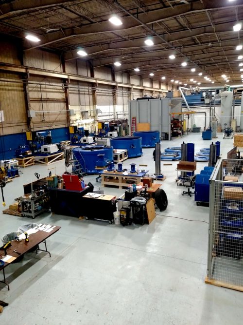
    Our latest expansion incorporates improvements in both the shipping and receiving department and the equipment build area. We’ve also recently acquired a new coordinate measuring machine (CMM)!

    • Spin Rig Assembly AreaShipping and receiving — To re-engineer the flow of parts coming into and out of our building, we relocated the shipping and receiving department to the front of the building to allow for expanded storage and handling areas along with additional cranes. In addition, the new area includes both plenty of space for trucks to back-in and an adjustable loading dock, allowing our forklifts to directly unload trailers. The relocation and improvements make unloading and loading operations significantly more efficient, contributing to reductions in turn-around time of customer parts.
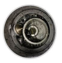

    • New coordinate measuring machine — To support the needs of our growing forging pre-spin business, we remodeled our climate-controlled precision inspection room, expanded the Quality Inspection team, and added a new larger Zeiss CMM machine.
    • Equipment build area — Because of the volume of recent spin rig orders, the equipment build & assembly area was relocated to a new section of the building. This update allows for new capabilities including improved setup and staging of the equipment builds and the ability to build three to four machines simultaneously. The improved build area also features an updated air supply and electrical supply for building and testing advanced machines.

    Learn More

    With an eye on quality services and constant innovation across everything we do, our Test Devices, Inc. team consistently strives to provide timely and efficient services to better meet our customers’ needs.

    An industry-leading provider of spin testing and balancing services, Test Devices is thrilled to announce these new facility updates, which will allow us to better serve our ever-expanding client base.

    For more information on these changes, or to discuss how we can help with your specific testing needs, contact the team today. We’re on hand to answer any questions you may have.

  5. Low Cycle Fatigue Rigs vs. Dynamic Spin Rigs

    Leave a Comment

    To validate the integrity of rotating parts against centrifugally loaded conditions, spin testing is a critical step to ensure rotor product quality. While the principle of the spin testing appears straightforward, it’s very easy to miss the important subtleties of the testing mechanics. In fact, since the early days of the spin testing, millions of dollars have been wasted and many perfectly good parts have been needlessly destroyed due to subpar testing practices.

    Successful spin testing requires participants to:

    1. Focus on the overall test objective – Which rotor features will the test assess, and under what conditions?spin rig comparison
    2. Understand the test part – How is the test part being assembled in relation to adjoined parts in the actual operating environment? How will it interact with those related components, how will those interactions mechanically or structurally constrain the test part while under assessment, and how is the spin tooling designed to accurately represent the condition?
    3. Recognize what to test for and what results will indicate – What measurements must be taken? How should these measurements be captured so that the resulting data is useful in understanding the failure mode, validating the engineering models, and updating the part design accordingly?

    Beyond the basics, spin testing can also be used to validate the durability of the rotors in more a realistic environment. Doing fatigue assessment in spin testing allows engineers to study part durability by using actual production parts (or modified versions), which would be more representative test specimens than coupons in terms of geometry, size and manufacturing process. Additionally, the loading condition resulting from the spinning would create realistic stress conditions, specifically related to the multi-axial loading field and the loading cycle.

    Test Devices, Inc. (TDI) and Schenck offer two different types of spin rigs for advanced fatigue assessment tests: a Low Cycle Fatigue Rig (LCF) and a Dynamic Spin Rig (DSR). Each style of rig is designed to accommodate specific testing requirements.

    • Low Cycle Fatigue Rigs are designed to perform various low cycle fatigue (LCF) tests, which are typically used to evaluate the overall durability of parts in terms of usage or operational cycles. For example, for a jet engine for a commercial airliner, this would be based on the number takeoff and landing cycles for a specified flight path.
    • Dynamic Spin Rigs, on the other hand, are designed to test the dynamic properties of the rotor parts and its high cycle fatigue (HCF) related failure modes. The HCF is a fatigue failure mode driven by the resonance of a part; for example, turbine blades may have resonances within an operating speed range that have modeshapes tied to incipient and rapid fatigue damages/failures.

    Low Cycle Fatigue (LCF) Rigs for Dependable and Realistic Testing

    test devices and schenck logosTDI offers unmatched performance and reliability in its advanced LCF test spin rigs. Featuring robust armor cylinders to ensure safety, a drive system with the rapid cycle time to expedite test schedules, and accurate cycle speed control system to hit cycle targets, the rigs have been continuously proven over Test Devices’ more than 40 years of testing experience.

    Combined with various automated testing features, Test Devices’ LCF rigs boast the highest-productivity drive systems available. These rigs typically incorporate a range of standard features, including:

    • Custom data acquisition system to record all test data
    • TDI’s proprietary crack detection system technology
    • Containment chamber designed to withstand high-energy burst failures
    • Vacuum system to eliminate aerodynamic losses and friction heat
    • Automated control system to perform various LCF test speed profiles
    • High performance drive systems with RPM capabilities of up to 250,000 rpm

    In addition to these features, LCF rigs can also be equipped with elevated temperature test capabilities, such as:

    • Isothermal – Uniform temperature on the test rotor
    • Thermal gradient – Capability to map the realistic “engine-like” rim-to-the bore temperature profile on the rotor

    Dynamic Spin Rig (DSR) for Advanced Turbine System Research

    High cycle fatigue (HCF) failure typically occurs during the critical phase of an aircraft’s operations, such as during the take-off for commercial airliners or rapid throttle changes in military aircraft. While the duration of an HCF-inducing condition exposure could be brief, the damage often develops rapidly before reaching a critical level. In most cases, there is no opportunity for correction once the condition reaches this point.

    DSR was developed to allow engineers to test and validate the dynamic property of bladed rotors at the component level, therefore minimizing test costs while still retaining the realism in the test. DSR are equipped with the capability to excite the bladed rotor with a desired dynamic load (of an Engine Orders, or EOs). The spin testing condition incorporates the effect of the centrifugal load on the test parts, which is known to affect its damping and resonance properties – this unique test element cannot be accurately replicated by traditional table-top methods.

    Test Device’s DSRs are equipped with unique testing capabilities, which include but are not limited to:

    • Proprietary high-precision tachometer & the rpm control system to “lock on” to the target resonances
    • Oil-jet and aero-pulse blade excitation systems
    • Multi-point strain gage & slip ring (or telemetry) systems
    • No-contact Stress Measurement System (NSMS), which is also known as the Blade Tip Timing system

    Testing Rigs from Test Devices

    With years of experience working with cutting-edge spin test rigs, Test Devices, Inc. is proud to provide testing services utilizing both low cycle fatigue and dynamic spin rigs to customers. To learn more about our LCF and DSR spin rigs, or to discuss options for your specific application, request a quote from the team today.

  6. The Testing Capabilities of Subscale Jet Engine Rigs – Part 1

    Leave a Comment

    A full-scale jet engine test provides both engineers and designers valuable and realistic data for developing and improving the design and the performances of critical rotating parts and the jet engines. However, performing a full-scale engine test is typically is an expensive and technically complicated affair.

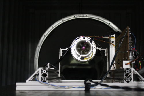
    Small Jet Engine Testing Rig

    Many engineers are still unaware of the various affordable engine test capabilities available through the use of subscale jet engines, such as oxidation/corrosion, creep/fatigue, blade high cycle fatigue (HCF), coating durability, fuel burn study, and volcanic ash/CMAS testing. In this blog, we’ll delve into oxidation & corrosion testing, creep & fatigue testing, and blade HCF testing in particular. For an in-depth look at the value of subscale testing in coating studies and oxidation and corrosion testing, be sure to check out the second part of this blog series, The Testing Capabilities of Subscale Jet Engine Rigs – Part 2.

    Oxidation and Corrosion Testing

    Oxidation — the reaction of oxygen in the gas stream with the surface coating or base metal of a part —  is the most common form of corrosion in aircraft engines. The result of chemical reactions by various elements of the engine core gas stream, corrosion causes the surface coating or base metal of a part to deteriorate. Corrosion can also be the result of galvanic action between mating parts.

    Oxidation and corrosion testing can be done more conveniently in a small scale by using an engine, and there are several ways to perform it. One can design and make a surrogate test turbine disk/bladed disk to fit in a microturbine, place a test specimen (a tile specimen or a test blade) in the exhaust gas stream, or design an extended exhaust section for the off-the-shelf turbine as a test section. Or, within the test section, a test rotor can be spun in the exhaust gas stream (by an independent drive).

    Creep and Fatigue Testing

    Materials, after being subjected to high temperature over a duration time may “creep”; a type of damage mechanism that results in a permanent deformation and initiation of cracks. Study of thermo-mechanical fatigue (TMF), a damage mechanism that combines the effect of the creep and the fatigue cracking, has been an active field of research amongst the aerospace community for some time. The TMF occurs when thermal and mechanical stress are cyclically applied to a part, resulting in a type of damages that shortens the useful life of the engines and hard to predict.

    While there are different types of test systems available to perform creep & TMF tests, many existing test systems, such as multi-axial tensile test rig, share the challenge of designing and manufacturing representative specimen that capture the intricate geometry and the features of complex high-temperature parts, for example, blades.  To further complicate the issue, the surfaces of high-temperature parts are often coated (EBC or TBC). Interaction of the coating system and the base material must be captured to accurately understand the failure mode.

    By using appropriately scaled turbine blade/disk specimens and using a subscale engine as a test vehicle, such a test could provide an affordable way to study the complex failure mechanisms in more realistic and economical manner. Also, subscale engine tests can cost-efficiently combine the effect of combustion gas elements (corrosion and oxidation) with earlier mentioned heat and mechanical load effects.

    Blade High Cycle Fatigue Testing

    A blade failure could severely damage or destroy a jet engine, exposing the aircraft and its passengers to an extremely dangerous and often lethal situation. One of the critical blade failure mechanism is the high cycle fatigue (HCF). The HCF is driven by the cyclic load caused by the interaction between the operational loads on the blades and their dynamic responses. HCF could result in a crack and could cause a blade to fail in a very short duration of time.

    Perhaps the most convenient and economical way to conduct a blade HCF test is by using a shaker table. Heating the blade helps to simulate the environment inside of the engine. However, shaker table tests severely limit the realism and it cannot capture the complex dynamics effects, such as the damping and response of CF loaded joints and traveling waves. To combine the effect of CF load to a shaker table test, engineers need to design a “representative” specimen shapes that can be mechanically pulled while retaining a “representative” dynamic response and loading conditions to the feature of interest.

    Historically, HCF has been a more prevalent problem for fan and the blades in the cold stages of the turbines (compressor). Driven by the efforts in reducing the component weight and improving the compressor performances, testing of the high-pressure compressor and lower turbine blades in elevated temperature HCF environment has become an interest of study for some engine OEMs. Traditionally, thicker and stubbier high-pressure turbine blades have not been a subject of HCF, however, this may change with the emergence of extremely high-temperature capable materials, such as CMC, that could open the opportunities for designing a thinner, lighter hot section blade technologies that would significantly cut weight and boost performances.

    A full-scale engine test would be a more realistic way to study HCF behavior but it would be very expensive. The use of a subscale engine could be a more affordable alternative – especially for a concept validation or R&D works. Subscale engine can be modified by using a purpose designed vanes, bladed rotor assemblies to study the HCF. Compare to the full-scale engine, it would be much easier to install and manage necessary sensors and instrumentation on a subscale engine. Spin testing might be a good option for HCF and blade dynamics testing, but we will leave this topic out for the interest of brevity of this blog.

    The Benefits of Small Rig Testing

    Subscale jet engine rig testing can be completed in a few months, whereas full-scale testing can take years. In fact, depending on number and complexity of tests required, most subscale testing can be completed in just two weeks. Easy customization provides an added bonus, enabling greater flexibility and quicker adjustments, and data from the tests are easier to compare with the model, allowing for greater insight into the condition of the engine. Also, these tests allow designs to be built from the ground up after engineers have a better understanding of test results — ensuring a top-quality, reliable design.

    Learn More

    To learn more about the benefits of small rig testing and the various jet engine testing capabilities available, download our free eBook, “The Importance of Subscale Jet Engine Testing.


    Download Our Subscale Jet Engine Testing Guide

    For information on how small-scale tests can help with your specific needs, contact our team of experts today.

  7. Keep Your Machinery Performing Optimally: Static and Dynamic Balancing

    Leave a Comment

    Rotating machinery is omnipresent in industrial use and seen in different fields all across the spectrum. Rotational systems and components are critical to the overall efficiency of businesses in industries such as aerospace, energy storage, automotive, electronics, and medical devices to name a few.

    Not sure what to look for in a balancing provider? Read our ebook below:

    "Download>”/>

    As the world continues to turn, industry experts rely more and more on rotating machinery to deliver fast, high-level and reliable results.

    These sorts of turbomachinery include pumps, compressors, fans, blowers, bearings, engines, motors, and more. An essential to keeping these machine types in optimal condition is awareness and maintenance of its balance.

    Understanding Unbalance

    Unbalance is known to be one of the most common sources of failure in rotating components and is caused by an uneven distribution of mass around the axis of rotation.

    When a system continues to rotate while unbalanced, it generates periodic forces perpendicular to the axis of rotation resulting in a vibration.

    Static and Dynamic Balancing

    This vibration becomes noisy and apparent as the severity of the unbalancing increases.

    Often, such a defect can be mistaken for a simple machine repair or bearing replacement; however, if noise and vibration continue after repairs then the machine is likely signaling that it needs to be balanced.

    If unbalance is detected in a rotational system, a balancing service is required to avoid structural defects and in extreme cases, catastrophic failure.

    Imbalanced rotational parts can result in excess wear and tear along with structural cracks that could massively affect long-run costs.

    A well-balanced turbomachine extends the bearing life and improves overall usage, quality, and accuracy of the machinery, which can be achieved through balancing services.

    Static vs. Dynamic

    Balancing services evaluate the components and provide a balance correction on materials like plastics or aerospace alloys. Based the type of machine or part, two balancing options can accurately restructure the assembly: Static and Dynamic.

    • Static Balancing is appropriate when an unbalance occurs at a single axial point on a disk-like rotor. In other words, the center of gravity of the object is on the axis of rotation allowing it to remain stationary with a horizontal axis and no braking force. The heavy point here is typically measured in relation to the component centerline.
    • Dynamic Balancing is appropriate for a dual plane unbalance with significant axial length and multi-rotor assemblies. In such a case, the rotation does not produce any resultant centrifugal force or couple and will rotate without application of an external force. Here, the two or more heavy points act independently on the mass centerline and unbalance must be corrected in two planes.

    Balance Correction

    Upon identifying the balancing service necessary, balance corrections can be done to bring rotational machines back to optimal performance levels. Balance corrections are mainly performed through material removal or mass addition at appropriate locations.

    The most commonly used material removal methods are drilling/milling and abrasive material removal. Drills or milling equipment are used to control depth and arch of material removal.

    For abrasive material removal, mass is removed through grinding or air-powered sanding equipment. Contrary to a removal process, a mass addition process can be implemented with epoxy, welding metal strips, or mechanical hardware.

    Balancing providers are not all created equal. Read our ebook below to find out what to look for:

    "Download>”/>

    Learn More

    Experts in rotational test systems and services are available to assure your machine’s success. These professionals are equipped with quality tools and systems to work with customer specifications for unparallelled spin testing and balancing services that can deliver results for the machinery’s optimal performance.

  8. Test Devices, Inc. Acquired by Schenck

    Leave a Comment

    To Deliver Increased Value and Testing Capabilities to Customers

    [Deer Park, New York. and Hudson, Mass.]  Sept. 28, 2017 –  Schenck Corporation (Schenck) and Test Devices, Inc. (TDI) announced today that they have reached a definitive agreement under which Schenck will acquire TDI in the form of a share deal from its current owner, Mr. H. Eric Sonnichsen.

    TDI is a leader in aviation-related testing technologies in the commercial and military sector, and is globally recognized for its proprietary, high-speed testing solutions. The company generated sales greater than $8 million in 2016.

    Schenck is an affiliated company of Germany-based Schenck RoTec GmbH. They are a leader in balancing and vibration diagnostic devices, with regional US offices in Detroit, MI, Chicago, IL, Houston, TX, Greenville, SC and Anaheim, CA. In addition, Schenck has a Mexican subsidiary with service cells in five main industrial areas. Its North American sales are about $50 million (globally around $250 million).

    “This acquisition adds tremendous consulting, prototyping and testing capabilities to our aerospace product line,” said Schenck President Ulrik Frodermann. “Together, TDI and Schenck will enhance customer value in a rapidly evolving aerospace industry by providing fast, cost-efficient, nondestructive or destructive testing methods, in the form of capital equipment or as an extended workbench.”

    “With three complementary balancing and spin testing centers in the US and ten additional centers globally, Schenck and TDI are uniquely positioned to support OEMs globally”, Frodermann continued. “Embedded in the German Dürr Group (2017 estimated turnover of more than $4 billion), these two companies will continue to innovate testing solutions and enable those solutions for the Industrial Internet of Things Platform (IIoT) ADAMOS, a consortium recently established of five German industrial powerhouses to facilitate the digital transformation of their product offerings.”

    “We are excited to become part of the Schenck and Dürr organization, which will enable TDI to deliver significantly more value to customers.  We look forward to further innovating in the domain of high-speed testing services and equipment, benefiting our customers by providing increased capability, and further assisting them in their ongoing efforts to advance their products” said Test Devices’ President David Woodford.

    Upon completion of the transaction, Schenck and TDI will continue their present product offerings, as two complementary brands with David Woodford retaining his position as President of TDI and Ulrik Frodermann, President of Schenck acting as the chairman of the supervisory board. Mr. Sonnichsen will continue to support the business as a Senior Engineering Consultant.


    About Schenck Corporation

    Schenck Corporation, Deer Park NY, a fully owned subsidiary of Schenck RoTec GmbH based in Darmstadt, Germany, provides high technology products and services to automotive and aerospace industries.

    Schenck RoTec is the world market leader in the field of balancing and diagnosis technology and has 17 subsidiaries and joint ventures with seven production sites worldwide. In addition, there are 44 representatives and offices on all five continents. The Schenck RoTec group supplies innovative technologies to important industries such as the automotive and supply industries, the electrical and electronics industry, aerospace, power station engineering and mechanical engineering.

    Schenck RoTec is part of Dürr group – one of the world’s leading mechanical and plant engineering firms with extensive automation expertise. Products, systems, and services offered by the Group enable highly efficient manufacturing processes in different industries. Dürr supplies sectors like the automotive industry, the mechanical engineering, chemical and pharmaceutical industries, and the woodworking industry. The company has 86 business locations in 28 countries. The Group generated sales of € 3.57 billion in 2016. Dürr has around 14,500 employees and operates in the market with five divisions:

    • Paint and Final Assembly Systems: paint shops and final assembly systems for the automotive industry
    • Application Technology: robot technologies for the automated application of paint, sealants, and adhesives
    • Clean Technology Systems: exhaust-air purification systems and energy efficiency technology
    • Measuring and Process Systems: balancing equipment as well as assembly, testing and filling technology
    • Woodworking Machinery and Systems: machinery and equipment for the woodworking industry


    Forward-Looking Statements

    This publication has been prepared independently by Schenck Corporation. It may contain statements which address such key issues as strategy, future financial results, events, competitive positions and product developments. Such forward-looking statements are subject to a number of risks, uncertainties and other factors, including, but not limited to those described in Dürr’s disclosures, in particular in the chapter entitled “Risks” in Dürr’s annual report. Should one or more of these risks, uncertainties and other factors materialize, or should underlying expectations not occur or assumptions prove incorrect, actual results, performances or achievements of Dürr may vary materially from those described in the relevant forward-looking statements. These statements may be identified by words such as “expect,” “want,” “anticipate,” “intend,” “plan,” “believe,” “seek,” “estimate,” “will,” “project” or words of similar meaning. Dürr neither intends, nor assumes any obligation, to update or revise its forward-looking statements regularly in light of developments which differ from those anticipated. Stated competitive positions are based on management estimates supported by information provided by specialized external agencies.


  9. Two Ways Improper Balancing Can Affect Your Profits

    Leave a Comment

    Unbalance is a naturally occurring, and expected phenomenon with all rotating components. It can occur suddenly, or build up over time, and is caused by any number of factors.  Distortions due to stress, uneven thermal distribution, or deposit build-up on the part are a few of the most common causes for unbalance in rotating machinery. Every rotating part will need to be balanced at some point within its lifespan, and it’s vital that the unbalance correction is performed properly.

    If you are unfamiliar with the balancing process, there is the possibility that your service provider can incorrectly “correct” the unbalance in your rotating component. This will occur when balance tooling and set-up are not properly developed, or the service provider’s personnel is not fully knowledgeable about the balance process required for the particular rotating component. An improperly balanced part (or batch of parts) can lead to severe consequences to your bottom line.

    Delays & Missed Deadlines

    As with all manufacturing processes, project schedules are extraordinarily sensitive. However, balancing services for the manufacturing industry usually occur at the very end of the component’s build process, right before delivery to the customer.

    If improper balancing occurs and is detected, there’s a high possibility that the delays will directly affect your client’s revenue for the month. So not only will you be paying for the rebalancing, but you run the risk of losing future contracts with your customer. However, the more realistic possibility is that the incorrect balancing is not caught in time, and the rotating components are shipped directly to your customer (which leads to the next potential hit to your bottom line).

    Non-Conformance & Part Failures

    When improper balancing occurs, it is close to impossible to detect immediately. This means that there is a high probability that non-conforming parts are entering the field. In a best case scenario, the unbalance is detected by your client when assembled into the final product, but before full product launch. You will not only incur the costs of transporting parts back and forth and the second round of balance correction, but you will also incur the metaphoric cost of lost faith from your client. It is also possible that the initial improper unbalance correction will be so severe that the parts will need to be scrapped – a catastrophic scenario for any profit margin. In the worst case scenario, total part failure will occur in the field as a result of an improperly balanced part. The costs of part failure in the field can be ruinous.

    The key to avoiding profit loss and potential part failures due to unbalance in your rotating components is in understanding what a good balance provider looks like and fully understanding the process.

    For more information on Test Devices Inc’s balancing services, please feel free to request a quote or contact us with any specific questions.

  10. Three Major Ways Your Manufactured Rotating Component Can Become Unbalanced

    Leave a Comment

    Unbalance in your rotating component is simply defined as the unequal distribution of weight along your rotor. It is a tricky problem that can sneak up on you unexpectedly. But with the proper knowledge, you can keep an eye out for the major causes of unbalance, and be prepared to address them quickly.

    Distortion from Stress

    Distortion can occur as a direct result of the manufacturing process and is often the result of a part “adjusting” to relieve stress. Manufacturing processes such as drawing, forging, pressing, etc. will yield internal stresses on parts. If stress relief is not built into the manufacturing process, the rotor will eventually distort to adjust to that residual, internal stress.

    Thermal Distortion 

    Change in temperature or uneven temperature distribution can also cause major distortions on a rotating part.  Most metals have the capacity to expand when exposed to heat, so when components operate within environments with elevated temperatures, there is the inherent possibility of expansion. If the heat exposure doesn’t happen uniformly over the entire part, certain sections will expand and distortion will occur.

    Thermal distortion is a common and natural occurrence with machines that are exposed to (or operate within) elevated temperatures, so components within machines like motors, compressors, turbines,  etc should be regularly evaluated for unbalance.

    Deposits & Oil Buildup

    If a rotating component is involved in any sort of material handling, it is almost inevitable that buildups of deposits will occur. Minerals (like lime), dirt or dust will begin to build up on rotating parts, cause an initial uneven distribution of weight, and vibrations will begin to occur.

    Rotating components that are exposed to oil (ie: lubricated compressors) are also highly susceptible to distortion. Oil has the ability to seep deep into components if left unchecked, and the liquid will accumulate until the buildup causes unbalance, vibrations, and sometimes part failure.

    (In the case of deposits and build-up, distortion CAN be avoided before unbalance occurs, if there is a stringent maintenance routine and/or inspection process implemented.)

    For more information on the balancing services that Test Devices Inc. provides check our Balancing Services Page or contact us directly.

    Or check out our most recent posts:

Have any questions?

Click Here
X