Skip to Content
Search Exit

Author Archives: Test Devices

  1. How Test Devices by SCHENCK is Leading the Trend on Improved Risk Mitigation

    Leave a Comment

    At Test Devices by SCHENCK, we’re committed to delivering industry-leading spin testing, machining and balancing services to our customers. Accomplishing this requires continuously adopting the latest technology and improving our operations. Our most recent investment has been in a new risk mitigation system, called Tulip, that’s helping us manage projects more accurately and efficiently than ever before. 

    Tulip is a cloud-based data management tool designed to display work instructions in an intuitive format and collect process data electronically. At Test Devices by SCHENCK we customized our Tulip tool to minimize the risk of logging incorrect process data or spinning parts to incorrect parameters. All information stored within Tulip is fully protected and not accessible by unauthorized parties inside and outside Test Devices by SCHENCK. With this new technology, we can easily scale up our services while simultaneously preventing mistakes and inaccuracies. 

    Our New Risk Mitigation System: Tulip

    Traditionally, testing services required paper instructions (routers/travelers) that had to be manually transcribed with the required information. With Tulip, these documents are replaced by a simple barcode. After our team receives your components, we attach a serial number that’s unique to the Tulip system. When it’s scanned, the app tells us all the information we need about your project, including: 

    • The current status of your part within the operation process including what area and who is working on it (ex/ Jim in shipping is packaging PN 1234 SN 5678)
    • The correct tools needed for each operation we perform and whether or not those tools have been calibrated according to the calibration schedule
    • Data on process parameters and measurements 
    • Real-time reports on the status of your work while it’s in progress 

    Another powerful advantage of this system is that it is fully auditable. We will maintain a complete record of every activity we perform, providing you with access to valuable raw data at any time. In the future, this information can be used to quickly review summarized testing reports or even compare data on parts over time to identify leading indicators of a process issue or differences between lots or machine shops. With these new capabilities, delivering parts that meet your quality standards is easier than ever. 

    How Our New System Improves Risk Mitigation

    Even in the hands of our expert team, paper-based work instructions often come with an increased risk of errors or omissions. They also make it more challenging to access data from your previous projects (no electronic database). The Tulip system is designed to eliminate these issues.

    When our team scans your parts, the Tulip system carefully guides them throughout the entire project. Enforced routing ensures that every step is completed in the correct order, with nothing skipped. The app also automatically verifies tolerance conformance and sends an alert when tooling has reached its limits.  

    With this technology, we can access real-time reports on the status of your project as it is in progress, and use this information to improve production planning and scheduling. The data we collect can be used to identify trends and potential problems early on, preventing costly delays and ensuring compliance with quality standards. 

    Turn to Test Devices by SCHENCK for Spin Testing, Balancing, and More

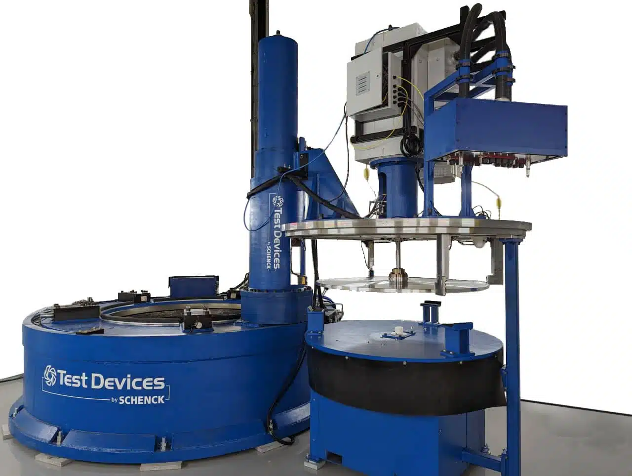
    At Test Devices by SCHENCK, we are a globally trusted source of quality spin testing and balancing services for high-speed rotating components. We strive to carefully review and understand our customers’ needs, working with them to create and simulate the most realistic test scenarios possible.

    We are continuously updating our procedures and capabilities to remain on the cutting edge of this demanding field. With our new risk mitigation system, we can help you improve the accuracy of your lifting models, shorten your testing programs, reduce the risk of engine test cell failures, and lower overall testing costs. 

    For more information about our Tulip risk mitigation system, or to get started on your spin testing and balancing solution, contact us or request a quote today.

  2. Boosting Precision with New Machining Equipment for Spin Testing

    Leave a Comment

    As an industry leader in spin testing, Test Devices by SCHENCK is a one-stop shop for even the most demanding projects. Recently, we’ve expanded our machining capabilities by investing in advanced turning equipment. Precision turning is a crucial aspect of spin testing procedures and our new machine, the OKUMA V760EX vertical lathe, allows us to refine large aerospace components with enhanced efficiency and precision. 

    At Test Devices by SCHENCK, we go beyond ordinary spin testing services by also offering CNC pre-spin machining and semi-finish machining. Combining these capabilities enables us to provide superior-quality components for customers in the aerospace industry. With our new machining equipment, we can deliver even greater precision in machining aerospace alloys. Below, you can learn more about how CNC machining services fit into the spin testing process and the new capabilities our OKUMA CNC lathe offers. 

    OKUMA V760EX Vertical Lathe 

    The OKUMA V760EX vertical lathe was designed with the needs of large part turning in mind, making it an ideal option for aerospace component manufacturing. It features massive construction and the high power capabilities needed to handle large-diameter workpieces.

    The vertical configuration of the OKUMA V760EX provides the advantages of natural part handling and excellent chip fall. Additionally, its larger work envelope allows for easier workpiece handling and faster access to tools, while taking up minimum floor space.

    How Our New OKUMA Vertical Lathe Levels Up Our Spin Testing Capabilities

    By enhancing our in-house spin testing services with CNC machining capabilities, our clients can obtain higher quality parts more efficiently than ever before. In the aerospace industry, every component must meet its required dimensions precisely. Even a small deviation can have catastrophic consequences. CNC machining is the ideal manufacturing method for these needs since it achieves extreme accuracy and precision. 

    The materials used in aerospace component manufacturing can be challenging to machine without specialized equipment. Aerospace alloys are often high-strength and uniquely formulated for extreme temperature resistance, creep resistance, and other demanding characteristics. Our new OKUMA vertical lathe features a rigid machine structure and a high-response positioning system for handling even the most challenging materials and geometries with ease. 

    The OKUMA V760EX achieves the following accuracies:

    • X-axis: 0.00059 in. (0.015 mm) over any 3.93 in. (100 mm) of stroke
    • Z-axis: 0.00098 in. (0.025mm) over any 11.81 in. (300 mm) of stroke

    Its repeatabilities include: 

    • X-axis: +/-0.00020 in. (+/-0.005 mm)
    • Z-axis: +/-0.00020 in. (+/-0.005 mm)

    The OKUMA V760EX vertical lathe features a maximum turning diameter of 29.92 in. and a maximum turning height of 30.31 in. It performs powerful, heavy-duty cuts while its vertical orientation is well-suited for creating thin-walled parts without distortion. In addition, it offers a milling function for added flexibility. Its box-type base and column provide a highly rigid and dependable structure, and its headstock with flange construction reduces the effects of vibration and thermal deformation for accurate, stable cutting. 

    Contact Test Devices by SCHENCK: Experts in Pre-Spin Machining Services and Spin Testing

    Test Devices by SCHENCK delivers industry-leading pre-spin machining and spin testing services. From our state-of-the-art facility in Hudson, Massachusetts, we meet the needs of a global customer base. We are AS9100 and ISO9001 certified to ensure you receive the best possible quality components, every time. Contact us to learn more about our CNC machining capabilities. If you’re ready to get started on your next project, request a quote today. 

  3. Benefits of Unbalance Budget Analysis for Rotors

    Leave a Comment

    While rotor balancing can sometimes be treated as an afterthought within the aerospace industry, rotor unbalance has a significant impact on overall machine performance, durability, and quality. When designing any rotating part, engineers must pay careful attention to the unbalance correction strategy. To optimize rotor design for improved performance, Andreas Buschbeck et al. from SCHENCK developed the Unbalance Budget Analysis method.

    The unbalance budget summarizes all reasons for the unbalance based on the given tolerance limits in the part drawings. Here, we’ll go over the key characteristics of rotor unbalance, as well as Buschbeck’s thoughts on why performing unbalance budget analysis is so crucial and how it’s accomplished.

    Characteristics of Rotor Unbalance

    Rotor unbalance can fall into three primary categories:

    • Intrinsic unbalance: A type of unbalance that results from variations in manufacturing tolerances or other factors relating to manufacturing technique.
    • Unbalance due to runout: An unbalance that comes from geometric variations in the shaft surfaces, particularly the mounting surfaces.
    • Unbalance due to fit clearance: This type of unbalance is due to fit clearance and is related to geometric variations in the assembly. For example, assembly misalignment can occur due to variations in the mating interface.

    Within all of these categories, there are many physical considerations that can result in unbalance. Controlling the level of unbalance in a rotating part requires a thorough definition of its reference features to which all shape and form tolerances can be compared.

    For instance, misalignment is a common cause of rotor unbalance. To define the acceptable level of misalignment a rotor can have, engineers must control the combined effect of geometric tolerances, including:

    • Concentricity
    • Coaxiality
    • Roundness
    • Lateral and radial runouts

    Reasons to Perform Unbalance Budget Analysis

    Rotor design requires an estimation of future unbalance correction which has to be applied for upcoming unbalances caused by geometric features and tolerance limits. This estimation helps to determine additional rotor features that allow the unbalance correction.

    Difficulties often arise when using design software that fails to account for unbalance or does not have the ability to achieve a balanced state for each rotor design. To overcome this challenge, a quantitative analysis method can be used to review the sensitivity of the abovementioned factors and correlate them to the rotor unbalance level. Based on the results of this analysis, it’s possible to understand which rotor features have the biggest impact on unbalance and correct them.

    A well-engineered rotor balancing strategy lowers costs and improves the manufacturing process by streamlining workflow. Additionally, it helps to determine which parts must be precision-machined to avoid unbalance and which can adhere to more rough geometric tolerance limits.

    Performing Unbalance Budget Analysis

    Several factors go into performing an unbalance budget analysis. First, an estimation and calculation of both initial and assembly unbalance must be performed for all relevant single components. This involves:

    • Estimating based on past experience with similar rotors
    • Determining the empirical value of manufacturing
    • Analyzing the drawing tolerances

    Many factors influence unbalance in single parts and assemblies, and these must also be considered. Engineers will review:

    • Manufacturing tolerances
    • Mass tolerances
    • Fitting tolerances and eccentricity respectively failure of concentricity
    • Coaxiality
    • Curvature and misalignment respectively axial run-out
    • Product of inertia of the single components around their center of gravity
    • Assembly of sub-components

    The final step is to consider any other potential cause of unbalance and then make a statistical summation of all of these factors and their significance. The summation should discuss both static unbalance and moment unbalance, as well as effects in the unbalance planes.

    Unbalance Budget Analysis: Required Data

    In the final analysis, there are many types of information that should be presented. This includes the measurement results (if available), all relevant part masses and densities, a description of the preliminary unbalance correction, and the distance between the bearings. In addition, 2D detail drawings with all geometric tolerances of all relevant rotating parts should be included. Finally, the analysis should feature 3D models of all relevant rotating parts as an assembly in either STEP or Parasolid (*.x_t) format.

    For a more in-depth look at performing an unbalance budget analysis, download our eBook, “Unbalance Budget Analysis: Optimizing Rotor Design for Manufacturing Performance.”

    Contact Test Devices for Balancing Services

    Performing a rotor unbalance budget analysis not only results in better-performing parts but can also reduce manufacturing costs. Gain a more in-depth understanding of this process by reaching out to our team with any questions. To get started improving the quality of your rotating parts, request a quote today.

  4. What Is Rotor Balancing and Why Is It Essential?

    Leave a Comment

    Rotors in rotor balance machineRotors are a critical component used to convert electric or electromagnetic energy into rotational motion. For rotors to operate reliably, they must maintain even weight distribution across the rotational axis. Too much weight on one side creates uneven mass distribution known as “unbalance“.

    Rotating parts in any mechanical assembly can become unbalanced. Uneven weight distribution of a rotating component causes the part’s rotational center to be out of alignment with the geometric axis. When unbalance occurs, the operational efficiency and safety of the system in which the rotor operates are compromised. Rotor balancing can help to prevent issues caused by unbalance, reducing noise and vibration and extending the life of your system.

    Have Questions ?

    What Are the Various Rotor Groups?

    Rotors are grouped into two categories: rigid and flexible. Rigid rotors can be balanced at lower speeds, as long as there is sufficient centrifugal force to detect the unbalance. Flexible rotors, on the other hand, deflect outward from the rotational axis, and the center of rotation moves away from the rotational axis as the speed increases. Unlike rigid rotors, flexible rotors must be balanced in stages, starting with lower speeds and slowly working up to operating speed.

    Why Is Rotor Balancing Essential?

    High levels of vibration caused by unbalance can cause equipment to operate less reliably, which results in increased energy usage, decreased operational efficiency, and reduced equipment service life. The force exerted by the dynamic load from an unbalanced rotor will cause wear to the rotor itself, the bearings and mountings holding it in place, and the machine’s structural support. Although the severity of the dynamic load varies depending on the degree of unbalance and the rotation speed, any unbalance can cause problems.

    Silver rotor balancing machine in operation

    Vibration from an unbalanced rotor creates excessive noise and resonance, which will ultimately compromise the structural integrity of the equipment that supports the rotor assembly. The damage caused by unbalance is especially apparent in bearings, suspension equipment, support housing, and the equipment foundation. These components are typically exposed to the highest level of stress caused by the excess dynamic load due to unbalance. With ongoing exposure, these components will be more likely to suffer premature wear.

    In addition, the high vibration caused by unbalance can loosen fasteners such as screws, nuts, and bolts, rendering the structure less stable. Pipes, electrical cables, wiring, electrical connections, and switches can also be negatively affected. With extended exposure to high levels of vibration, even nearby equipment and structures can be compromised, creating the potential for greater damage and injury.

    What Are the Various Types of Unbalance?

    When balancing your rotor, it is critical to understand the different types of unbalance. There are three types of unbalance, including:

    1. Static Unbalance: This type of unbalance occurs when the mass axis is displaced parallel to the shaft axis. Static unbalance is corrected only in one axial plane.
    2. Couple Unbalance: Couple unbalance occurs when the mass axis intersects with the running axis. This type of unbalance is typically corrected in two axial planes.
    3. Dynamic Unbalance: Dynamic unbalance is typically a combination of static and couple unbalance and occurs when the mass axis does not intersect with the rotational axis. This can usually be repaired by correcting the balance along two axial planes.

    Contact Test Devices by SCHENCK

    Rotor balancing being performed by machine on white background
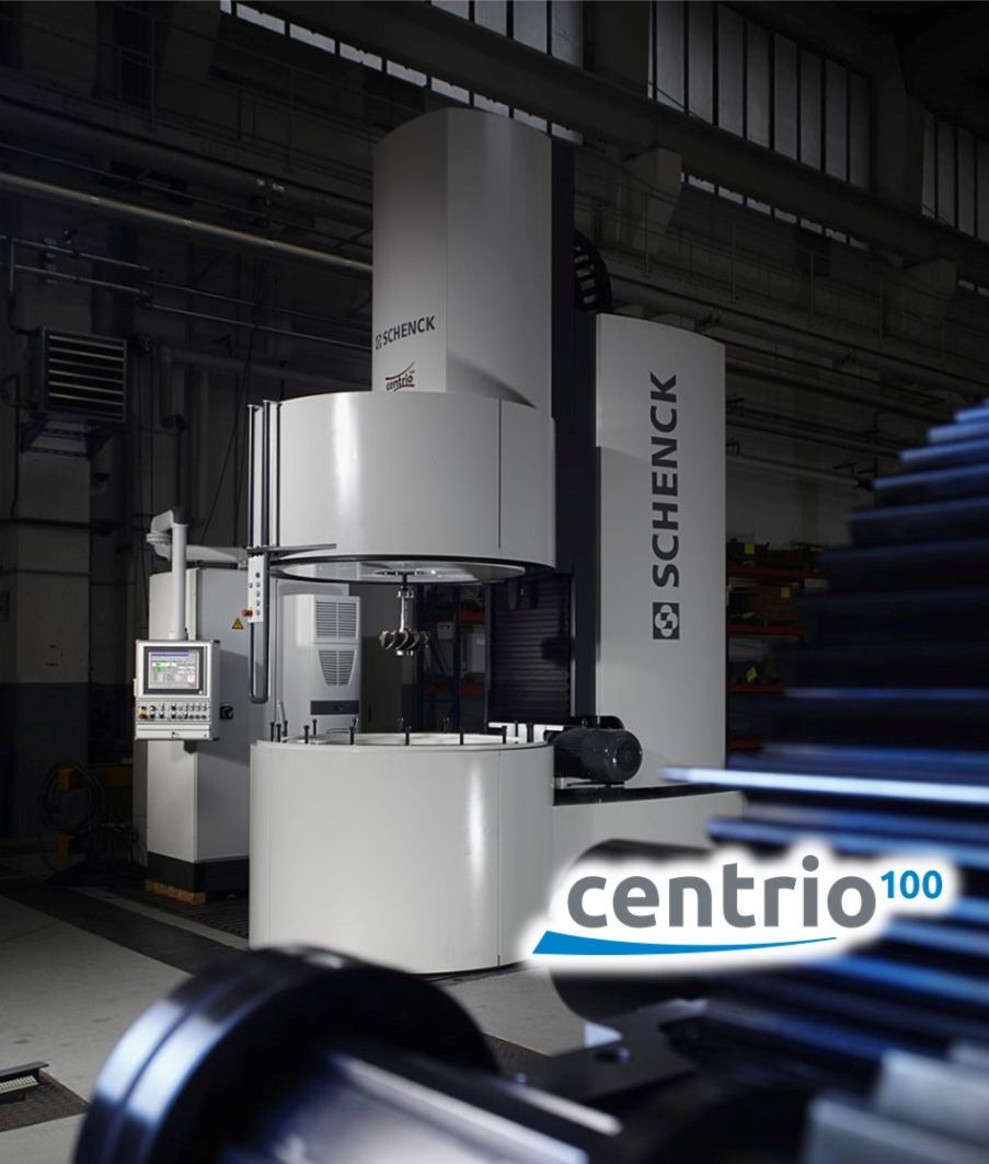
At Test Devices by SCHENCK, we are dedicated to providing our customers with expert balancing solutions for rotating and oscillating equipment in a wide range of applications and industries. With more than 50 years of experience, we have the knowledge, equipment, and skill necessary to provide superior balancing services for everything from modular drills to industrial crankshafts and wind power turbines. We are skilled in servicing equipment of all sizes, from miniature dental motors of only a few ounces to 400-ton steam turbine rotors.

    Our expertise extends to dynamic balancing, static balancing, couple balancing, and much more. With an international team of over 900 experts, we work tirelessly to design, research, develop, and produce actionable balancing solutions for customers in the automotive, aerospace, electrical, and mechanical engineering industries. In addition, we offer maintenance services and quality control testing to ensure that your rotor equipment is operating within applicable industry standards and regulatory guidelines.

    We are committed to providing superior rotor balancing services to our customers around the world. To learn more, contact us today.

    Figure 1,  A Rigid Test Rotor mounted on a Schenck Hard Bearing Balancing Machine.


  5. Test Devices by SCHENCK Sponsors Award-Winning WPI Rocket Team

    Leave a Comment

    SCHENCK Sponsors Award-Winning WPI Rocket Team

    As part of our commitment to promote STEM, Test Devices by SCHENCK has been a proud sponsor of the Worcester Polytechnic Institute (WPI) High Power Rocketry Club. This student organization runs educational workshops on topics such as rocketry and robotics and also enters intercollegiate engineering competitions. Recently, the team has been winning impressive awards and gaining visible results.

    What is the WPI HPRC?

    The WPI HPRC is Worcester Polytechnic Institute’s High Power Rocketry Club, a student organization dedicated to rocket engineering and STEM education. A large portion of the club’s time is devoted to pursuing hands-on learning as they design, build, test and launch sounding rockets. The HPRC also believes that taking part in high-level competitions is an important aspect of cultivating technical expertise in the next generation of engineers.

    Participating in rocketry competitions allows this group to develop a more in-depth knowledge of the engineering design process. HPRC members come from diverse backgrounds and disciplines and are able to channel their unique experiences into engaging collaborative projects. Over the years, club interest has grown and today the HPRC includes a member base of over 200 students. Every member actively participates in managerial or technical tasks, fostering an inclusive and engaged educational environment. An important aspect of the HPRC is to cultivate leadership skills as they work as a team in a professional and intense goal-oriented atmosphere for students to navigate.

    WPI’s Competition Journey

    SCHENCK Sponsors Award-Winning WPI Rocket Team

    WPI’s High Power Rocketry Club originated in 2018 with the founding of the WPI University Student Launch Initiative (USLI). That year, WPI’s team competed in NASA’s annual USLI competition. Enthusiastic student response led to the first competition rocketry launch the following year with Project G.O.A.T.S. The goal for this launch was a target apogee of 4,094 ft.; however, failure occurred at 800 ft.

    After a year of delays due to the COVID-19 pandemic, WPI re-entered the competition scene in 2021 with a new and improved rocket for Project Sirius and Polaris. This project’s test bed launch was instrumental in preparing for the team’s most demanding competition yet, the 2022 Spaceport America Cup’s Intercollegiate Rocket Engineering Competition. Hosted by the Experimental Sounding Rocket Association, 158 teams from 24 countries participated in the world’s largest intercollegiate rocket engineering competition.

    At this event, nearly 2,000 students from around the globe gathered to share their passion for high-power rocketry. In 2022, WPI’s rocket team experienced launch failure at this event, they used lessons learned from the setback to improve their rocket design and came back with more skill than ever before in 2023.

    Today, with only five years of operational experience, WPI has obtained advanced technical aptitude and emerged as a leading competitor in the world’s most challenging rocketry competitions, like the SAC IREC. In 2024, the team plans to compete in the 10K Solid Commercial Off-the-Shelf Division at the SAC IREC. Their mission is to launch the team’s high-power rocket and payload system to an apogee of 10,000 ft. with another successful recovery.

    Competition Success and Awards

    Throughout HPRC’s history, they have experienced many impressive achievements and awards. Each year as they participate in challenging international competitions, they demonstrate an impressive dedication to engineering excellence. The team has attended the Spaceport America Cup’s Intercollegiate Rocket Engineering Competition (SAC IREC) annually since 2021, collecting new awards each year. Their past competition successes include:

    • SAC IREC 2022 Team Sportsmanship Award
    • SAC IREC 2023 3rd Place Payload Challenge Award, Space Dynamics Laboratory
    • SAC IREC 2023 Jim Furfaro Award for Technical Excellence

    Most recently, in 2023, the club obtained 2.64% within their 10,000 ft. target apogee. This feat allowed them to beat out over 100 internationally competing teams to win two awards for technical achievement. As a platinum-level sponsor, Test Devices by SCHENCK is proud to support the WPI HPRC and its efforts to foster engineering excellence in our local community.

    Learn More About Test Devices by SCHENCK: Leading the Way in Rotational Parts

    At Test Devices by SCHENCK, we’re passionate about innovative technology and work continuously to advance the science of rotational testing. Taking part in community outreach programs is an important part of this mission. In addition to supporting WPI’s rocketry team, we also host local students for aerospace industry events. Here, we share knowledge about our work, promote STEM education, and inspire the next generation of scientists and engineers. Explore our website to learn more about what we do and contact us with any questions. If you have a project you’d like to work with us on, request a quote today.

  6. The Value of Fatigue Testing

    Leave a Comment

    Fatigue testing machine with low angle

    Fatigue testing is a crucial procedure used by engineers and technicians to help predict the durability of a part or component under its operating conditions. To appreciate the value of fatigue testing, it is essential to first understand this testing service.

    Fatigue is a type of structural damage prevalent in cyclically loaded structures. The fatigue is characterized by an initiation and growth of cracks that will eventually result in a catastrophic fracture of a material. Unlike the structural failure caused by an overload, fatigue damage develops under the magnitude of the stresses below the material’s yield strength, and therefore tends to covertly manifest without deforming or showing obvious “warning signs”. The rate at which a fatigue crack grows is dependent on the material’s properties as well as the intensity and cycle frequency of the applied load.

    Fatigue testing is used to evaluate a material’s (and component’s) structural durability by testing and analyzing its ability to withstand cyclic loading conditions.

    Fatigue Testing Methods

    There are different types of fatigue testing machines with various capabilities, ranging from automated material specimen tensile test machines to large full-scale structural test rigs. In a rotating structure, such as gas turbine disks and blades, accurately capturing the loading conditions in fatigue-prone features can be a complicated challenge. Rotors often have intricate geometries to serve its intended functions and these features are subject to varying degree of multiaxial stresses caused by the CF load, which also changes over the course of the operating cycle of the machine as rotor speed changes. These loading conditions are difficult, if not impossible, to capture in test methods other than spin testing.

    Within the rotor specific testing techniques, Test Devices Inc. is specialized in performing different variants of LCF (Low Cycle Fatigue) and HCF (High Cycle Fatigue) tests.

    The LCF regime is characterized by a higher load application, within the material’s elastic-plastic range, at low frequency (or cycle rate). For example, the take-off and landing cycle of an airplane. Typically, the HCF regime is characterized by the application of a very high-frequency load which results in a rapid accumulation of fatigue damages in a short span of time. These conditions are found in the vibrating vanes or blades subject to resonance.

    Both LCF and HCF are common issues in the operation and safety of critical rotating components. Unexpected failure of rotors, such as high-speed impellers and turbine engines, which operate under high centrifugal forces often end in a catastrophic effect.

    Benefits of Spin Fatigue Testing

    Fatigue testing is performed to generate the data needed to validate and/or refine a probabilistic model of the components’ life in its operational environment. The way the fatigue damage initiates and develops in a material can be influenced by various factors including the loading field cycle pattern, axiality, temperature and environmental factors (e.g. oxidation and corrosion).

    The result of the fatigue test data helps to define the maintenance and repair cycle requirements and the safe operating life of machines. These will have a significant impact on the cost of ownership of the equipment as well as safety-related issues.

    Test Devices specializes in providing the most relevant test data to our customers who design and develop the advanced machines that are critical to our transportation, infrastructure, and national defense.

    Spin fatigue testing can be used in any industry or application where the durability and integrity of a rotor and rotating component matters. Some industries that regularly use fatigue testing and fatigue testing machines include:

    • Automotive – Turbochargers, tires, and wheels
    • Aerospace – Jet engine components, turbine rotors, wing materials
    • Medical – Prosthetics, implants

    Learn More From Test Devices, Inc.

    At Test Devices Inc., we offer both low-cycle and high-cycle fatigue spin testing services for clients who work with high-speed rotating components in demanding environments. We are capable of testing various complex and cutting-edge machinery parts for jet engines, electric motors, turbomachinery, and energy storage systems.

    Our qualified and experienced engineers are willing to assist you in fatigue testing your unique part or component. If you would like to learn more about our testing services, feel free to contact our support team today.

  7. How To Avoid Major Causes of Unbalanced Parts

    Leave a Comment

    Person working on rotor balance machinery
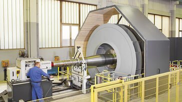
Unbalanced components can lead to electrical motor failures that necessitate costly investigation, repairs, or replacement. The easiest way to avoid this is to properly balance the rotor during the manufacturing stage.

    Unbalance happens when a rotating component’s center of mass, or inertia axis, becomes unaligned with its center of rotation, or geometric axis. It causes the rotating component to exert dynamic load on its supports, shaft, and connected structures. Here, we will discuss some common causes of unbalance and how to correct them as well as why it’s important to have balanced parts.

    What Causes the Unbalance of Parts to Occur?

    In general, all cases of unbalance result from the uneven distribution of mass around a rotation axis. However, this unevenness can be caused by various factors, including the buildup of contaminants, assembly errors, dimensional and mass deviation in the parts, deformation of the parts, and normal wear of moving parts. Other factors that might contribute to unbalance include some unintended change caused by maintenance repairs, replacing a part, or incorrect placement of a part.

    Since unbalance is a leading cause of premature failure in a rotating machine, it’s important to take the necessary steps to correct or prevent it.

    How Do We Correct Unbalanced Parts?

    To avoid further damage, balance correction must be carefully planned and performed. Two ways to correct unbalanced parts include material removal and material addition. Which method we use depends on the cause of the unbalance and the design of the parts.

    Material Removal

    The material removal method relies on abrasion, milling, or drilling processes. With the abrasion process, air-powered sanding or manual grinding tools are used to remove material; however, milling and drilling offer enhanced control. Material removal tooling must be able to remove the right amount of material from the correct place and to the proper depth without damaging nearby parts. At Test Devices, we use specially designed and calibrated milling equipment to remove material while maintaining high levels of precision and a superior finish.

    Material Addition

    Material addition methods solve unbalance by adding various correction features on the rotor, such as blades, inserts, washers, or screws. In some cases, we may weld material to the rotor or add epoxy coatings.

    Why Is It So Crucial to Have Balanced Parts?

    Small individual rotor balancing machine
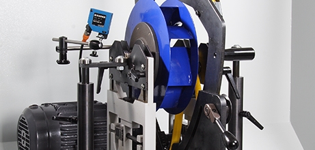
Unresolved balance issues can lead to serious consequences for you and your client, ranging from quality issues, significant schedule setbacks. Unbalance can lead to higher vibration and noise levels in machines, affecting their overall efficiency and quality.

    When left undetected, unbalanced rotors can lead to high maintenance and repair costs. In an extreme scenario, an unbalanced part from your facility could end up in a live field environment, where part failure can have disastrous consequences.

    Balancing Services from Test Devices

    Avoiding and correcting unbalance is crucial in preventing premature part failure in electrical motors. At Test Devices, we have provided high-quality balancing services for over 40 years. We are AS9100/ISO9001 certified, and our balancing services support a wide range of industry standards. To learn more about our balancing capabilities, contact us today.

  8. Testing for eMotors: A Case Study

    Leave a Comment

    Custom spin rigHigh-speed rotating components in eMotors require accurate spin testing to ensure safety, reliability, and performance. At Test Devices by SCHENCK, we offer the most advanced balancing and spin testing services on the market. View the case studies below for a better look into how we serve clients in the electric mobility industry with our expert testing capabilities.

    EV Case Study

    A prominent automotive OEM client approached SCHENCK to test a new rotor design for an EV drive system. The team at Test Devices by SCHENCK designed and performed a spin test to evaluate the at-speed behavior of the rotor in its operating environment (including temperature).

    The data collected in-situ during the spin test, as well as the pre- and post-test precision unbalance measurements revealed unexpected structural instability that would have otherwise compromised the quality and performance of the client’s end product.

    The experts at SCHENCK and Test Devices worked with the client to thoroughly analyze the data and identify any potential root causes. Doing so allowed us to alleviate the issue and improve the overall rotor design.

    E-Propulsion Case Study

    A leading aero-propulsion OEM client has been working with Test Devices by SCHENCK to test a rotor for a new eVTOL propulsion system. We have spin tested several prototypes to identify the at-speed behaviors of each rotor under its operating conditions. 

    During the spin testing process, we measure the change in the rotor outer diameter (OD), or inner diameter (ID) if accessible. Using this data, we can determine the average growth or create a growth map as a circumferential deformation profile (expansion measurement). The former helps us understand the bulk material behavior of the rotor, and the latter provides a visualization of the deformation shape at speed.

    We measured the rotor deformation shape with SCHENCK’s Rotor Expansion Measurement System (REMS). Analyzing this data allowed us to identify undesirable inter-part interactions that required modification prior to finalizing the design for production release. By detecting design and manufacturing flaws at the prototype stage, we were able to help the customer avoid expensive and painful in-field issues.

    Contact Test Devices for Spin Testing Services

    Test Devices by SCHENCK has extensive experience performing various spin tests for electric vehicles, eVTOLs, ePropulsion, eDrive and eMobility applications. From our state-of-the-art facility in Hudson, Massachusetts, we offer industry-leading spin testing equipment and services for clients around the world.

    Our expert team is dedicated to providing superior-quality products and services that meet or exceed customer requirements. We achieve this through ISO 9001 and AS9100 certification, process and product innovation, and continuous improvement of our quality management system.

    For more information about our spin testing capabilities for eMotors, contact us or request a quote today.


  9. Spin Testing Improves ePropulsion Rotor Design

    Leave a Comment

    Developing sustainable transportation solutions is an increasingly high-priority goal in the aviation industry. Amongst the emerging contenders of electrified aircraft, exciting trends include the development of delivery drones and air taxis (eVTOLs). These new vehicles are designed to fly at low altitudes over heavily populated areas, requiring focused attention on its electric propulsion systems for noise minimization and design redundancy that provides safe-to-fail measures. 

    The demand for more efficient and power-dense electric propulsion systems is set to increase steadily. To make them flight-worthy, makers of propulsion systems must fulfill the airworthiness requirements, which typically require rigorous analysis and validation testing. 

    Test Devices by SCHENCK supports these emerging technologies with industry-leading spin testing services. These services aid in design development and the eventual certification of ePropulsion rotors. This article will discuss the types of spin tests involved in electric propulsion testing, the benefits associated with these services, and what the future holds for eVTOL certification. 

    What is a Spin Pit?

    centrio 100 spin testerThe rotating parts in eVTOL motors are critical to safety and operation, and they must be thoroughly tested before they can enter into service. Typically for a flight-worthiness certification, critical rotating parts in aircraft are tested for their structural integrity and fatigue durability. Whether it is an overspeed test or Low Cycle Fatigue (LCF) test, the parts are pushed close to their strength and durability limits, and it is not uncommon for them to fail during the test. High-speed rotors store a significant level of kinetic energy, and they often fail suddenly and violently. If not prepared, the rotor failure event could result in a catastrophic event.

    A spin pit is a purpose-designed machine specialized in testing high-speed rotors safely. 

    At Test Devices by SCHENCK, we perform various types of spin tests for electric propulsion rotors by using our purpose-designed spin pit. The latest model of Schenck’s Centrio 100 spin tester features a fortified test chamber designed to contain hazardous rotor bursts and their subsequent fragments while offering many automated features to streamline the setup and execution of tests. The system also offers various test conditions (ex. elevated temperature conditions) and advanced data measurement options (such as a rotor expansion measurement system).

    Why Spin Test?

    Compared to other testing methods, spin testing reveals important data about rotor design. Some of the key benefits of spin testing include:

    • Cost and schedule benefits. Since spin testing tests the rotor by itself, there is no need for additional auxiliary hardware such as the bearings, stator, or VFD. Compared to a full-system test, spin testing offers a more pragmatic and economical method to set up the desired test conditions and instrument the rotor for data measurements. This is especially true when a rotor needs to be tested outside of its typical design envelope.
    • Risk management. As explained earlier, the spin pit addresses the safety risks associated with a rotor burst. In addition, spin testing also alleviates the risk of premature test termination from the failures of auxiliary systems or parts.  
    • Early phase evaluation. Spin testing allows engineers to test variations of rotor design separately from other components or subsystems. Doing so enables engineers to generate useful engineering data to fill the information gap and optimize the rotor design. The data can be used to mature the numerical model, accelerate design maturation, and boost confidence in first article success.

    Spin tests provide critical data and information to evaluate the performance, safety, and operation of critical rotating parts. Doing so saves time and helps to avoid costly and painstaking investigative work that could emerge as a result of partially validated rotor designs. Partnering with an industry expert like Test Devices by SCHENCK can help you bridge the information gap and accelerate your product development cycle. 

    Types of Spin Tests

    When testing ePropulsion rotor design, there are three types of spin testing methods: overspeed, burst, and LCF testing. Each of these testing services offers unique information on the durability and structural integrity of a rotor’s design. 

    Overspeed Test

    Also known as a proof test, the goal of an overspeed test is to validate structural stability and integrity. Overspeed testing is performed by spinning a rotor above its typical operating ceiling. During the process, the rotor will be examined for several changes in behavior: 

    • Linear elastic or plastic deformation
    • Changes in unbalance level
    • Changes in the rotor outer diameter (OD) profile

    As a result of this testing process, we can help minimize the risk of unexpected rotor dynamic instabilities and confirm the rotor’s structural integrity. 

    Burst Test

    A burst test involves spinning a rotor until it ruptures under a centrifugal (CF) load. The goal is to observe and confirm the limit and the failure mode of the rotor, as this information is key for improving its safety and structural integrity. During a burst test, a high-speed video camera setup within the spin pit captures imaging of the burst event. An in-depth understanding of the rotor’s failure mode can give key insight into a better-performing design.  

    Low Cycle Fatigue (LCF) Test

    LCF testing is an important method of evaluating a rotor’s durability. It involves cycling the rotor through tens of thousands of speed cycles, either in ambient or elevated temperature conditions.

    The test temperature for electric motor LCF test is typically in a low threshold (200°F-500°F). However, this does not diminish the importance of accurately controlling the test temperature, as its effect is relative to the material property of the rotor. At Test Devices, we take extra care to avoid unintentional heat damage that could compromise the accuracy of the test result. 

    Benefits of Using Test Devices by SCHENCK’s Spin Testing Services for ePropulsion

    At Test Devices by SCHENCK, we offer everything you need for ePropulsion rotor testing and balancing. Our extensive background in spin testing for ePropulsion systems delivers many benefits for our clients, including: 

    • Full engineering support from test concept development to project management and final reports
    • Access to a world-class testing facility with an onsite machine shop for expeditious hardware adjustments
    • Test instrumentation expertise, including expansion measurement and high-speed video imaging
    • Pre- and post-test inspection capabilities, including balance measurements and CMMs
    • Testing standards that adhere to the AS9100 aerospace standard

    The Future of Spin Testing for Electric Motors

    Modern spin testing techniques for electric motors offer valuable data for accelerating and advancing state-of-the-art rotor designs for high-performance electric motors. eVTOL motor rotors are complex assemblies that feature composite structures (vs. homogenous) that make them difficult to model.

    The data from spin testing bridges this information gap, serving as a proven technique for CF load testing and offering a variety of test environments and data measurement options. The data derived from spin tests enhance rotor safety while helping tune the analytical models and deepen the understanding of rotor behavior and failure modes. Spin tests also allow earlier testing to be performed, eliminating assumptions and uncertainties while smoothing the path toward eVTOL certification. 

    Spin Testing Services From Test Devices by SCHENCK

    Test Devices by SCHENCK is a global leader in balancing technologies and high-speed rotor engineering. Our spin testing services are a critical element of manufacturing high-quality rotating parts that deliver greater efficiency and increased service life. As a partner in climate-neutral mobility, we can help you develop eMobility solutions that reduce environmental pollution and noise emissions. For more information on our electric motor testing services, contact us or request a quote today.

  10. New ISO Certifications

    Leave a Comment

    At Test Devices by SCHENCK, we have an unparalleled and proven reputation for innovation and safety. We deliver the world’s most accurate and advanced spin testing services and equipment to clients in various industries, including aerospace, automotive, energy, defense, electric motors, medical, and commercial space. To illustrate our commitment to safety and the environment, we’re proud to have acquired our ISO 14001:2015 and ISO 45001:2018 certifications.

    ISO 14001:2015: Environmental Management Systems

    ISO 14001:2015 outlines the requirements for an Environmental Management System (EMS) that a business can use to improve its environmental performance. More specifically, it requires that you maintain proper documentation that proves your EMS meets the required standards. It outlines clear requirements regarding the type of documentation you must provide but does not dictate how you must record the evidence or how to operate your EMS. 

    The primary purpose of the documentation is to ensure an organization maintains robust environmental processes. These documents also illustrate that your entire organization acknowledges and is working towards your environmental objectives and goals. The ISO 14001:2015 certification is essential for organizations seeking to systematically manage their environmental responsibilities and uphold their dedication to sustainability. 

    Why is it Important? 

    ISO 14001:2015 is important because it helps businesses achieve the intended goals of their EMS, providing value for the organization itself, the environment, and any interested parties. Intended outcomes of an EMS include:

    • Achievement of environmental objectives
    • Fulfillment of compliance obligations
    • Improvement of environmental performance

    ISO 45001:2018: Occupational Health and Safety Management Systems

    ISO 45001:2018 highlights the requirements for an organization’s occupational health and safety (OH&S) management system.SCHENCK USA ISO 14001 Certificate By providing direction for the use of OH&S management systems, this standard helps businesses provide a safe and healthy work environment by preventing work-related illness and injury. 

    Why is it Important?

    The ISO 45001:2018 standard can be used partially or in its entirety to improve OH&S performance. However, an organization will only be able to claim conformity to the standard if every requirement is incorporated into its OH&S management system and is fulfilled. These requirements include:

    • The development of investigation processes
    • Reporting any nonconformities and OH&S incidents to create corrective action plans
    • Documentation of any activities and corrective actions to further improve plan development and ensure effectiveness


    Which of Our Services Do These Certifications Affect?

    Having these certifications improves our ability to provide safe and environmentally conscious services, including:

    Spin Testing Services

    At Test Devices by SCHENCK, we offer spin testing services to customers that work with high-speed rotating components found in cutting-edge machines that face challenging conditions. These components are often found in high-speed electric motors, turbomachinery, jet engines, and energy storage systems. We serve a wide range of clients, including the world’s leading OEMs, with innovative solutions that solve challenging issues in manufacturing spin processes and engineering testing. Our spin testing and rotor balancing services support critical engine part certifications, design validations, and manufacturing processes. 

    Balancing Services

    Unbalanced rotating components can result in catastrophic machine failure as well as harm to personnel and machinery. Accurately balancing a rotor requires a high level of expertise. Not all service providers are the same, and it’s important to work with a balancing provider that is capable of providing the necessary level of consistency and quality. At Test Devices by SCHENCK, we can provide precise balancing surfaces to prevent further issues that could otherwise lead to higher costs.

    Green Technology

    SCHENCK’s spin testing and balancing services for the green technology industry are part of a worldwide movement to reduce noise and air pollution caused by traditional transportation. The goal is to mitigate and adapt transportation to address climate change. Electric vehicles and electric vertical take-off and landing (eVTOL) aircraft are just two examples that are gaining ground in their respective industries.

    ISO Certified Spin Test Services and Equipment From Test Devices by SCHENCK

    Test Devices by SCHENCK offers ISO 14001:2015 and ISO 45001:2018-certified spin testing services and equipment to clients across several industries. By acquiring these certifications, we further illustrate our dedication to quality, safety, and environmental sustainability. Whether you require spin testing or balancing, our experts are here to deliver innovative solutions that meet your needs. For more information about our ISO certifications, or to learn more about our service capabilities, request a quote today or contact us at 978-562-6017. 

Have any questions?

Click Here
X