


Optical Strain Measurement
Optical strain measurement is a strain measurement method based on digital image processing. The method is a non-contact measurement technique, which alleviates the need for modifying the parts for lead-wire routing and sensor attachment as required in traditional strain gage instrumentation. Less time wasted and facilitates a quicker, more efficient testing process.
The optical strain method helps engineers to understand the full picture of strain behavior. Providing a detailed map of the strain field rather than having to rely on a single-point measurement with a presumed correlation to an analytical model result. The optical strain system provides superior data for optimizing and enhancing the design and material selection for parts in high performance machines.
At Test Devices, we’ve developed an application for the optical strain technique for high speed rotating parts. This innovative and forward-thinking process presented a clear opportunity for us to offer our clients an improved view of the performance and capability of their parts.
Understanding the Fundamentals of Optical Strain Measurement
Optical strain measurement techniques have existed for a long time. Practical use of the technique became more realistic with the recent strides in the realm of digital imaging technologies and computation power which started to match the requirement for the image processing-based measurement techniques.
Various strain mapping techniques have increased in popularity in recent years. They rely on information about how printed patterns or features on the surfaces of objects move as the part deforms; and, from this information, they calculate the surface strain of the part.
Rotor Optical Strain System (ROSS), which was developed at TDI, we designate a target area on the surface of the test rotor. The area is marked with an engineered pattern. Strain data can be calculated from the captured images via a digital image correlation (DIC) technique. Thanks to a proprietary de-rotating system, which allows capturing of suitable images for strain map computation.
Why ROSS?
ROSS offers numerous advantages compared to pre-existing methodologies. These include:
- Capturing fuller maps of the strain field
- Eliminating the assumptions that are inherent in single-point measurement techniques (e.g. straingages)
- No requirement for modifying the test part for attaching sensors and routing of leadwires
- Non-contact measurement technique
- Cuts preparation time and expedites test schedules
- Reduces cost and potential risk of an unexpected failure
- Straingages and leadwires are subject to sudden failure from G-load forces
- Risk of slip ring malfunction or failure, especially at high rpm
At Test Devices, we offer full-field data with ROSS that gives our clients superior insight into the understanding of strain behavior in test parts. The data unlocks the path to fuller understanding of material behavior, design performance, and failure mechanisms.
We believe that a full-field approach to data measurement technologies is essential. The future development of high-performance machine components is dependent on processes like these.
If you’re looking to learn more about our optical strain measurement capabilities, request a quote today.
The Issue
Traditional strain measurement techniques collect data only from a selected number of locations. Decisions on where to locate strain gages are typically based on analytical models or “educated guesses.” Often, the manner in which a gage is mounted, and the interpretation of the resulting data, is a topic of debate.
Why It Matters
The bonding of strain gages and lead wires in traditional testing makes the process of traditional strain measurement both costly and time-consuming. Bonded strain gages and lead wires are subject to large “g” forces on rotating hardware, and often to elevated temperature conditions. Unfortunately, gages may occasionally detach during testing, compromising the data obtained. It is very difficult to strain gage “tight” locations reliably. Furthermore, bonding a gage to a small feature could alter its deflection upon loading.
What You Can Do
Test Devices’ customers can now capture strain data over a full component during spin testing. Optical strain measurement can measure and record surface strain at thousands of locations simultaneously. Collected data can act as a standalone resource, or to supplement data generated by traditional in-situ methods such as strain gaging, growth probes and post-test dimensional measurement. The strain map generated with an optical system provides a richer and more complete picture of any component deformation. Optical strain measurement is ideal for studying small or complex component features such as turbine blades and impellers. 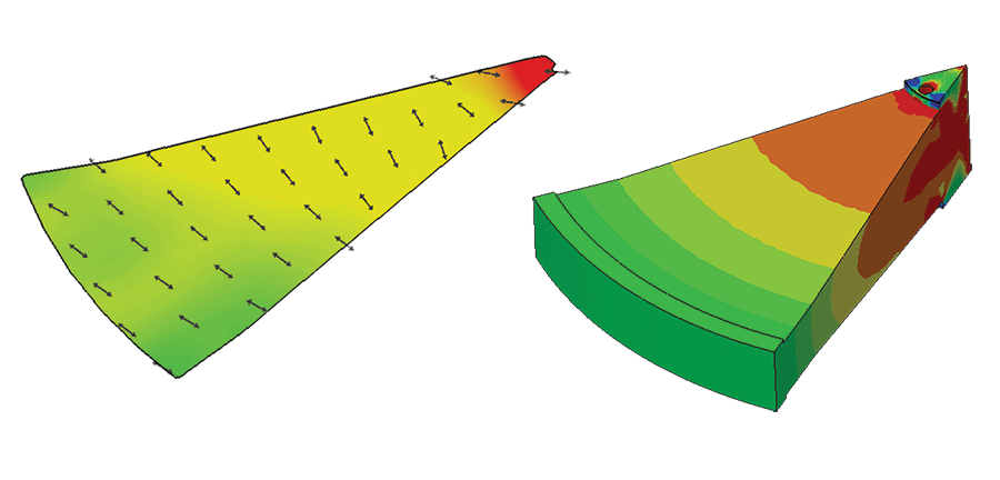 Figure 1 – Optical Strain Measurement
Advantages of Optical Strain Measurement
Reduced cost and ease of test set-up: Eliminating gages and lead wires allows engineers to easily modify, inspect or reconfigure a test (e.g. swapping turbine blades).
Reduced risk: As a non-contact technique, optical strain measurement eliminates the costly, time-consuming process associated with bonding of strain gages and lead wires in traditional testing. Data accrued during optical strain measurement is less likely to be compromised, as gage detachment is not a factor.
Greater applicability: Optical strain measurement equipment can be set up in stand-off positions; outside of a test chamber entirely, if sightline ports are available. This enables strain measurement during testing under extreme conditions (e.g. high temperatures or aggressive environments) that would damage contact and proximity gages. Optical strain measurement has been used for over a decade on static components. Applying it to very high-speed rotational components is relatively new, so Test Devices is addressing challenges and developing improvements to make optical strain measurement an economical “go-to” tool for a wide range of high-speed testing and production applications.


