


Production/Proof (‘Burst’) Rigs
Overview
Proof/Burst Spin Test Systems are used to perform a few specific spin tests. Proof tests (also known as “over-speed” and “pre-spin” tests) are typically run to prove component integrity following preliminary machining or component repair, or for pre-stressing rotors prior to final machining. Burst tests are run to establish the operation safety margin for components and understand the mechanism by which components fail (failure analysis).
Test Devices’ Proof/Burst Spin Test Systems incorporate all basic spin pit capabilities in an efficient and cost-effective system to perform proof or burst tests of high-speed rotating components to meet R & D or production requirements.
Standard Modules
Containment Chamber: Industry leading containment capability designed for high energy applications.
Vacuum System: Includes the pump/blower set, providing a vacuum level below 400 milliTorr, together with controls and level gauge.
Drive Systems: Test Devices offers a range of drive options for both air turbine drive systems and direct electric motor drive systems, covering the speed range up to 160,000 rpm. Our 600 Series turbines are designed specifically for proof and burst testing applications.
Key Features
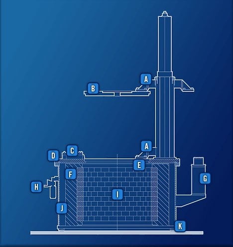
- Lid Lift
- Lid
- Lid Dog
- Cover
- Lead Brick Retainer Ledge
- Forged Steel Armor Liner
- Air Float Counterbalance
- Air Regulator
- Lead Brick Liner
- Casing
- Leveling Wedges
Armor Cylinder – Primary Containment
A robust armor cylinder is mandatory for long-term safety of the machine and the operator. The steel armor cylinder Test Devices uses for the primary containment of an uncontrolled burst is forged and heat treated. The single piece forging eliminates welds, reducing stress concentration and strength issues. It is designed to yield only under overload conditions, with an 18% elongation.
Test Devices designs armor cylinders to be fully elastic in both shear and tension, and they are reinforced at the top and bottom by a retention ledge. This feature strengthens the ends of the cylinder and prevents the extrusion of the soft lead inner liner against the covers.
Casing
The casing is fabricated from high strength steel. It encloses the entire test chamber and sustains a vacuum using airtight seals. The inside of the casing is larger than the outside diameter of the armor cylinder to allow the inner safety liner to expand if overloaded. This extra room allows the containment cylinder to stretch and absorb energy without ruining the vacuum chamber during an exceptionally high energy burst.
Options
Data Acquisition
All test data (e.g., temperature, speed, vibration, strain) are recorded on a custom digital data acquisition system.


